/
TABLE OF CONTENTS TABLE OF CONTENTS

TABLE OF CONTENTS - PDF document

conchita-marotz
conchita-marotz . @conchita-marotz
Follow
391 views
Uploaded On 2016-05-15

TABLE OF CONTENTS - PPT Presentation

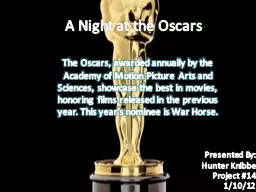
1 INTRODUCTION 1 2 AIMS OF THE MIZ1 BOREHOLE INVESTIGATIONS 3 3 LOCATION AND LAYOUT OF THE MIZ1 BOREHOLE 4 4 BACKGROUND INFORMATION AND PREDICTED CONDITIONS FOR PlANNING OF THE MIZ1 BOREHOLE ID: 321359

INTRODUCTION

Share:

Link:

Embed:

Download Presentation from below link

Download Pdf The PPT/PDF document "TABLE OF CONTENTS" is the property of its rightful owner. Permission is granted to download and print the materials on this web site for personal, non-commercial use only, and to display it on your personal computer provided you do not modify the materials and that you retain all copyright notices contained in the materials. By downloading content from our website, you accept the terms of this agreement.


Presentation Transcript

TABLE OF CONTENTS 1 INTRODUCTION 1 2 AIMS OF THE MIZ-1 BOREHOLE INVESTIGATIONS 3 3 LOCATION AND LAYOUT OF THE MIZ-1 BOREHOLE 4 4 BACKGROUND INFORMATION AND PREDICTED CONDITIONS FOR PlANNING OF THE MIZ-1 BOREHOLE INVESTIGATIONS 7 5 DETAILS OF THE MIZ-1 BOREHOLE INVESTIGATIONS 26 5.1 Borehole Drilling 26 5.1.1 Aims 26 5.1.2 Methodology 26 5.1.3 Reporting 27 5.2 Geological Investigations 29 5.2.1 Aims 29 5.2.2 Methods 29 5.2.3 Planned field work 29 5.2.3.1 Work during drilling 29 5.2.3.2 Work after drilling 30 5.2.4 Planned laboratory work 30 5.2.5 Reporting 31 5.2.5.1 Field work reports 31 5.2.5.2 Laboratory work reports 31 5.3 Geophysical Investigations 33 5.3.1 Aims 33 5.3.2 Methods 33 5.3.3 Planned field work 33 5.3.4 Reporting 34 5.3.4.1 Geophysical logging 34 5.3.4.2 Borehole TV 34 5.4 Hydrogeological Investigations 35 5.4.1 Aims 35 5.4.2 Methods 35 5.4.3 Planned field work 35 5.4.3.1 Work during drilling 35 5.4.3.2 Work after drilling 37 5.4.4 Reporting 37 5.5 Hydrochemical Investigations 39 5.5.1 Aims 39 5.5.2 Methods 39 5.5.3 Planned field work 39 5.5.4 Planned laboratory work 39 5.5.5 Reporting 42 5.5.5.1 Field work reports 42 5.5.5.2 Laboratory work report 42 ii LIST OF FIGURES Figure 1: Location of the MIU construction and Shobasama sites 2 Figure 2: Location and projected trace of the planned MIZ-1 borehole 5 Figure 3: Location of the MIZ-1 and existing boreholes 6 Figure 4: View of the MIZ-1 drilling site 6 Figure 5: Topography around the MIU construction site 7 Figure 6: Geological map around the MIU construction site 9 Figure 7: Uranium occurrences around the MIU construction site 10 Figure 8: 3-D view of surface topography of the Toki granite around the MIU construction site 10 Figure 9: Cumulative fracture frequency in the MIU-2 borehole 11 Figure 10: Relationship in thickness between UHFD and sedimentary cover 11 Figure 11: Comparison of fracture frequency of low-angle fractures in the DH-2 borehole and reflection seismic data around the DH-2 borehole 11 Figure 12: Distribution of known faults and inferred major faults (IMF) crossing the site around the MIU construction site 12 Figure 13: Water inflow points identified by fluid logging in the DH-2 borehole 13 Figure 14: Predicted geological profiles along the MIZ-1 borehole (Representative model) 14 Figure 15: Predicted geological profiles along the MIZ-1 borehole (Uncertainty model) 15 Figure 16: Topography and head distribution at –1,000masl 17 Figure 17: Groundwater flow lines through the deep underground below the MIU construction site, based on regional-scale groundwater flow models 17 Figure 18: Location of major drilling fluid loss in UHFD 18 Figure 19: Transmissivity profile along the DH-2 borehole 18 Figure 20: Hydraulic conductivities in the Toki granite 19 Figure 21: Predicted hydrogeological conditions along the MIZ-1 borehole 19 Figure 22: Depth profile of hydrochemical data in sedimentary rocks 21 Figure 23: Depth profile of hydrochemical data in Toki granite 21 Figure 24: Chlorine content in rock core at MSB-2 borehole 22 Figure 25: Eh-pH diagrams for the Fe-O 2 -S-CO 2 -H 2 O system at 25C and 1 bar (Activity of Fe species = 10 -6 . Fugacity of CO 2 (g) = 10 -5 . Activity of S species = 10 -5 .) 22 Figure 26: 36 Cl/Cl versus Cl concentrations for selected groundwater samples 23 Figure 27: Conceptual hydrochemical model 23 iv SECTION 1 1 INTRODUCTION In the Mizunami Underground Research Laboratory (MIU) project, a wide range of geoscientific research and development activities are planned to be performed in three phases, Surface-based Investigations (Phase I), Construction (Phase II) and Operations (Phase III), over a period of 20 years. Surface-based investigations have been conducted at the Shobasama site since 1997, in accordance with the report “Master Plan of the MIU” (PNC, 1996). However, JNC could not obtain an agreement from the local community for beginning construction of the MIU facilities. Therefore, in July 2001, Mizunami City proposed lease of City land at a new site for construction of the MIU facility. JNC decided to accept the proposal and concluded an agreement with Mizunami City in January 2002 (Figure 1). Surface-based investigations at the new MIU construction site began in March 2002 (JNC, 2002). Main goals of the MIU project are: • • • • • To establish comprehensive techniques for investigating the geological environment, and To develop a range of engineering techniques for deep underground applications. The specific goals of the surface-based investigations are, To construct geological models of the geological environment based on the surface-based investigations and develop an understanding of the deep geological environment (undisturbed, initial conditions) before excavation of the shaft and experimental drifts To formulate detailed design and plans for the construction of the shaft and experimental drifts, and To plan scientific investigations during the construction phase. Figure 1 Location of the MIU construction and Shobasama sites 1 SECTION 1 Three scales of surface investigation are considered for both the Regional Hydrogeological Study (RHS) project and the MIU Project. The RHS is a major geosciences project in the greater area around the MIU site. The three scales are: • • • Regional scale (over 10-km square), Local scale (several km square), and Block scale (several 100-m square). Investigations in the MIU project are mainly performed at the block scale while those in the RHS are related to the regional and local scales. Field investigations during the surface-based investigations phase are planned for completion by the end of 2004, with excavation of the main shaft, Phase 2 construction, planned to start in December 2004 or January 2005. The diameter of the main shaft has provisionally been set at 6 meters and the proposed depth is 1,000 meters. Details of the geometry and depth of specific underground facilities, including the main shaft, the ventilation shaft and the drifts, will be defined using data on the geological environment obtained during the surface-based investigation phase. As part of the surface-based investigations at the MIU construction site, outcrop geological mapping and a reflection seismic survey at and around the site were carried out. Shallow borehole investigations and hydrogeological investigations in the DH-2 borehole started in April 2002 in order to characterize the sedimentary cover rocks and the upper, approximately 332 meters of the crystalline basement respectively. Taking into account the status of the investigations as of August 2002 and the remaining time (i.e., two and a half years) for the surface-based investigations, an optimized program for MIZ-1 borehole investigations has been drawn-up. This program addresses the key issues (e.g., identification and characterization of water-conducting features deep underground) and provides input to the subsequent investigation programs and design for the shaft and experimental drifts. This document mainly describes the planned working program for the MIZ-1 borehole investigations including associated laboratory programs during and after drilling. The working program is divided into the following investigation fields: borehole drilling, geology, geophysics, hydrogeology, hydrochemistry and long-term monitoring. Post-MIZ-1 borehole investigations; a VSP (Vertical Seismic Profiling) survey, rock mechanical field investigations and laboratory tests, cross-hole seismic tomography and hydraulic testing between the MIZ-1 and DH-2 boreholes are planned in the surface-based investigations phase. An outline of these investigation programs is provided in the appendices to this document. 2 SECTION 3 3 LOCATION AND LAYOUT OF THE MIZ-1 BOREHOLE The MIZ-1 borehole will be drilled in an overall southwesterly direction (S46°W; azimuth 224 o ) from the northeast part of the MIU construction site (Figure 2 and 3). The inclination or plunge will vary with depth, based on the inclination control plan described below, which will enable the borehole investigation program to be optimized. - Drill vertically from surface to approximately 250mabh. As discussed in Section 4, there is a good possibility of intersecting a zone in which major drilling fluid loss may occur at about 30masl, in the UHFD. Drilling to 250mabh will ensure that if the zone is intersected, MIZ-1 will drill past the zone before starting the controlled directional drilling. - From 250mabh to 460mabh, using controlled directional drilling, the borehole will curve in a southwesterly direction, with inclination decreasing from vertical in increments of 1.5 degrees every 30mabh. The inclination target is 12 degrees from vertical. - From 460mabh to 1,350mabh, drill to southwest at 78 degrees inclination from horizontal. This controlled directional drilling results in an offset from the borehole collar of about 207m at the bottom and a true vertical depth of about 1,329m. The following restrictions and requirements were considered in planning the location and layout of the MIZ-1 borehole. Restrictions: - Borehole must be within the MIU construction site and cannot cross the site boundary at any depth. - Obstruction to the MIU facility construction work should be avoided. Requirements: - Attempt to intersect inferred major faults considered to exist in the Toki granite at the MIU construction site and to study their geological properties. - Less fractured, relatively hard granite is more amenable to controlled directional drilling than is highly fractured or soft rock. Therefore, for this technical reason, intersection of faults during the controlled directional drilling should be avoided. - The true vertical depth must be over 1,000m to acquire information on the deep geological environment. 4 SECTION 4 4 BACKGROUND INFORMATION AND PREDICTED CONDITIONS FOR PLANNING OF THE MIZ-1 BOREHOLE INVESTIGATIONS JNC has obtained extensive information on the geology, hydrogeology, hydrochemistry and rock mechanical properties in the Tono area through the MIU project at the Shobasama site, at the MIU construction site, in the RHS project and from the Tono Mine studies. The information is useful in characterizing the geological environment, especially of the crystalline basement, in the MIU construction site. Based on compilation and interpretation of the data, summarized information related to the geological environment in the MIU construction site and predicted conditions in the MIZ-1 borehole are presented here: Topography - The overall topographic gradient across the MIU construction site is approximately 5% from NE to SW in the local-scale area (Figure 5). - The main rivers at or near the site are the Toki, Hiyoshi and Garaishi Rivers, and together with their branches for the main drainage basins. The Toki River basin is the largest basin, the Garaishi River basin drains into the Hiyoshi River basin which in turn drains into the Toki River basin. - The MIU construction site comprises small ridges and valleys derived by erosion of the main NNE-SSW trending ridge in the west, and a narrow fluvial plain along the Hazama River in the east. Elevation (m) MIU construction site 0 1000 m Elevation (m) MIU construction site 0 1000 m 0 1000 m Figure 5 Topography around the MIU construction site 7 SECTION 4 Geology Sedimentary cover - Tertiary sedimentary rocks (the Miocene Mizunami Group and the Pliocene Seto Group) unconformably overlie the eroded Cretaceous crystalline basement (the Toki granite) with varying thickness from 100 to 180m at the site (Figure 6) (JNC, 1999). - The Mizunami Group is stratigraphically divided into the Toki Lignite-bearing Formation, the Akeyo Formation and the Oidawara Formation, in ascending order. Relatively low concentrations of uranium mineralization (0.01 to 0.05wt% of U 3 O 8 ) are found in the basal conglomerate layer of the Toki Lignite-bearing Formation along the northwest trending paleochannel caused by erosion of the Toki granite (Figure 7) (PNC, 1988). Basement granite - The eroded surface of the Toki granite varies significantly in elevation from 25 to 200masl at the MIU construction site. West of the site, the channel is narrow and steep, possibly indicative of rapids or falls (Figure 8) with depth, except for the weathered zone at the top of the granite and two hydrothermal alteration zones. The weathered zone, which is about 1m thick, is characterized by overall argillic alteration and precipitation of iron oxyhydroxides. Two hydrothermal alteration zones suggest acid hydrothermal fluid circulation (i.e. sericite alteration) along major fault zones in past. - Two structural domains, an upper highly fractured domain (UHFD) and a lower sparsely fractured domain (LSFD), have been distinguished in the Toki granite based on the fracture frequency data from boreholes at the Shobasama site (Figure 9) (JNC, 2001). Based on the consistency in thickness between the UHFD and the sedimentary cover observed in boreholes at the Shobasama site, the thickness of the UHFD expected at the MIU construction site is estimated to range from 270 to 349m (Figure 10). - Two intensely fracture zones, named the jointed zone and characterized by a high frequency of low-angle fractures, have been identified in the UHFD intersected by the DH-2 borehole. Comparison of the borehole data with the seismic data shows there is a consistency in shape and distance between the jointed zones and the granite surface (Figure 11). This seems to indicate that the zone may extend across the site. Major faults and water conducting features - From the prior investigations (lineament analyses, reconnaissance survey, reflection seismic surveys, shallow borehole investigations, DH-2 borehole investigations), 12 inferred major faults (IMF) are believed to be present and cross the site (Figure 12). - The 19 water inflow points identified by fluid logging in the DH-2 borehole investigations are considered to be water conducting feature (WCF). Of these, 84% of the water inflow points are related to major fracture zones, that is, related to the major faults and the jointed zones (Figure 13). Prediction of the geology in the MIZ-1 borehole - Based on the compilation and interpretation of the existing geological information, a predicted geological profile along the MIZ-1 borehole is produced (Figure 14 and Figure 15). The profile shows the major geological intersections expected such as the unconformity, the weathered zone, the jointed zone, two structural domains and three inferred major faults (IMF03, IMF10 and IMF11). Most of WCFs in the MIZ-1 borehole are expected to be related to the inferred major faults and the jointed zone. 8 SECTION 4 Figure 7Uranium occurrences around the MIU construction site Figure 8 3-D view of surface topography of the Toki granite around the MIU construction site 10 SECTION 4 Figure 12 Distribution of known faults and inferred major faults (IMF) crossing the site around the MIU construction site 12 SECTION 4 Figure 13 Water inflow points identified by fluid logging in the DH-2 borehole 13 SECTION 4 Figure 14 Predicted geological profiles along the MIZ-1 borehole (Representative model) 14 Figure 21 Predicted hydrogeological conditions along the MIZ-1 borehole (b) Distribution of hydraulic conductivit of the UHFD and LSFD SECTION 4 boreholes. Prediction of hydrochemistry in the MIZ-1 borehole - Based on the existing information, a conceptual model for groundwater chemistry in the area is presented in Figure 27. The groundwater evolution is possibly controlled by mixing process between low-salinity groundwater (Na-Ca-HCO3 and Na-HCO3 type) in the upper parts of the sedimentary rocks and higher-salinity groundwater (Na-Cl type) in deep granite. In the MIZ-1 borehole, groundwater chemistry is expected to evolve from low-salinity groundwater to relatively high-salinity groundwater with depth. The Eh values of groundwater are also expected to change from slightly (~0mV) to strongly reducing conditions (-300~-400mV) in the Toki granite with increasing depth. Figure 22 Depth profiles of hydrochemical data in sedimentary rocks Figure 23 Depth profiles of hydrochemical data in the Toki granite 21 SECTION 4 Figure 26 36 Cl/Cl versus Cl concentrations for selected groundwater samples Oidawara Formation A ke y o Formation Toki Li g nite-bearin g Formation Toki Granite Basal Conglomerate Na-Cl-HCO3 typepH:8 Eh: ?mV Na-Cl typepH:9~10 Eh:-300~-400mV Na-HCO3 typepH:9~10 Eh:-300~-400mV Na-Ca-HCO3 typepH:~8 Eh:~0mV Na-Ca-HCO3 type? Na-HCO3 type? Mixing? DH-11 DH-12 Toki River MIUconstruction site Elevation(masl) 300 200 100 0 -00 -200 DH-2 -300 Figure 27 Conceptual hydrochemical model 23 SECTION 4 (a) Horizontal principal stresses (b) Direction of maximum horizontal stress Figure 28 Profiles of in-situ stress state along boreholes at the Shobasama site Figure 29 Conceptual geomechanical model at the Shobasama site 25 SECTION 5 5 DETAILS OF THE MIZ-1 BOREHOLE INVESTIGATIONS In the MIZ-1 borehole investigation program, a wide range of investigations are planned (Figure 30). The following subsections (5.1 to 5.6) provide the details of the “base case” program in each investigation field. The procedure and schedule for the “base case” investigation campaign is described in Section 6.1.1, and optional cases are discussed in Section 6.1.2. 5.1 Borehole Drilling The MIZ-1 borehole investigations comprise the deep borehole program in the MIU construction site. The main objective is to intersect several defined targets, namely inferred major faults (IMF 03, IMF 10 and IMF 11) and to develop an understanding of the geological environment to approximately 1,330mbgl, in the Toki granite. Full core recovery and stable borehole conditions are required for the on-site geological, hydrogeological and hydrochemical investigations. A triple barrel-core recovery technique with an acrylic innermost core barrel was successfully employed in the MIU-4 borehole investigations to ensure high percentage core recovery and maintain borehole integrity. It is intended to apply this method to the MIZ-1 drilling program. 5.1.1 Aims - Full core recovery for geological, hydrogeological, hydrochemical and geochemical investigations. - Provide suitable locations for downhole investigations such as hydraulic tests, groundwater sampling and borehole logging. 5.1.2 Methodology The MIZ-1 borehole will be drilled in six phases (see section 6.1.1). The following methodology will be used. Casing and cementing The surface soil and the friable top of the Mizunami Group will be drilled to a depth of 5mabh using a tricone bit. Borehole diameter will be 26 inches (660.4mm) with 20 inch (508.0mm) casing pipes installed to 5mabh and fixed by full hole cementing. Continuous core drilling will be done from 5mabh to about 114mabh that is through the Mizunami Group, the weathered zone and into the UHFD in Toki granite. Following borehole investigations in this interval, the interval from 5mabh to 106mabh will be reamed using a tricone bit or an air hammer to a diameter of 17- 1/2 inch (444.5mm). Then, either 14 inch (355.6mm) or 13-3/8 inch (339.7mm) casing pipes will be installed and fixed by full hole cementing. Dredging and flushing of the borehole are performed after cementing. The borehole is flushed with drilling fluid tagged with fluorescent dye (see Drilling/flushing fluid below). For further drilling, 6 inch (165.2mm) temporary casing is installed to 106mabh. Coring Wireline core drilling, 5-1/2 inch (136mm) diameter and using fresh water is performed from 5mabh to the final depth at 1,350mabh. A triple-barrel drilling method with an acrylic inner core barrel is employed for full or high percentage core recovery. The core diameter, except during the controlled directional drilling, is about 85mm. Intact core is extracted from the acrylic tubes and orientated. An orientation line is marked on the core. 26 SECTION 5 Status of the field work (drilling length, water level and tests performed, etc.) is reported by fax, by the on-site drilling inspector. Daily report (to be supplied to JNC on the next morning) Duration and time of drilling, personnel, activities undertaken, drilling length, tally list of drill strings and measurement or testing tools used, results of deviation surveys, bit life, details of machinery used, consumption of supplies and anything abnormal or unexpected are reported promptly. Final report (by the end of the contract period) A complete record of drilling is reported in detail with logs of drilling data. 28 SECTION 5 fracture density, location and dip of fracture (log), shape of fracture, structure on fracture plane, nature of alteration products along fracture, width of fracture and mineralogy of fracture filling materials including identification of potential flowing features. Depths where the core is cut for storage and good packer locations for hydraulic tests are also recorded. Borehole profiles, including all this information, will serve as a basis for other investigations. Photographs of all cores are taken using a camera to preserve visual geological and structural information. All images include a scale and a color chart. Each image includes up to five, 1m long lengths of core. Core scanning and sampling (in house) Images of cores are taken with a digital scanning device using optical wavelengths for later numerical analysis of fractures. Samples for later laboratory work are then selected after the evaluation of information obtained during drilling. 5.2.3.2 Work after drilling Core sampling (in house) Samples for further laboratory work are selected based upon information obtained by previous investigations. 5.2.4 Planned laboratory work The following laboratory work is planned. Details (e.g. constituents, methods and numbers of samples for analysis) are summarized in Table 1. Petrological characterization (by contractor) Standard optical microscopy is conducted on rock thin sections to clarify lithological characteristics of the Toki granite. Any correlation between such geological information and fracture density, hydraulic and physical properties is identified and discussed in the report. Petrological characterization (in house) Mineralogical and structural characteristics of fracture fillings and of altered wall rocks are described by means of microscopic examination of thin sections. Classification of WCFs is also made on the basis of microscopic examination and on-site core description. In addition, grain size distributions and mineral compositions of the granite matrix and of the fracture fillings are determined by the combined use of XRD (X-Ray Diffraction), XRF (X-Ray Fluorescence spectroscopy), and conventional modal analysis (e.g. point-counting). Mineralogical characterization (in house) Paragenesis of fracture fillings is investigated by detailed examination using optical microscopy and SEM (Scanning Electron Microscope). Chemical compositions of major fracture-filling minerals and of the constituent minerals of associated wall rocks are determined by EPMA (Electron Probe Micro-Analyzer) techniques. Geochemical characterization (by individual contractor and in house) Major components and trace elements including REEs (Rare Earth Elements) are analyzed on both granite samples and fracture fillings by XRF, IC (Ion Chromatography), ICP-MS (Inductively Coupled Plasma-Mass Spectrometry) and by wet chemical methods. The aims of these analyses are to characterize the Toki granite at the MIU site as thoroughly as possible for geological modeling and to provide geochemical data on WCFs for interpreting water-rock interactions. Stable isotope compositions (or isotopic ratios) are also determined on fracture fillings by various mass spectrometric techniques. Such isotopic data, together with data on geometry 30 SECTION 5 Final report (by the end of contract period) All results are reported with full data sets. Full details of all methods employed, operating conditions of equipment, relevant detection limits and precision are described. Details are also given of anything unexpected that occurred during the laboratory work Table 1 Planned laboratory work for geological investigations Constituents Methods* Sample** Quantity Laboratories GM FF/AW Remarks Petrological Characterization Petrography Optical microscopy 25 30 JNC, Contractor Mineral composition XRD, XRF, Modal analysis, Photo-processing 25 30 JNC Mineralogical Characterization Chemical composition EPMA – 30 JNC Paragenesis Optical microscopy, SEM – 30 JNC Geochemical Characterization Major components SiO 2 , TiO 2 , Al 2 O 3 , Fe 2 O 3 , FeO, MnO, MgO, CaO, Na 2 O, K 2 O, P 2 O 5 , H 2 O+, H 2 O-, CO 2 XRF, IC, ICP-MS, Wet chemical analysis 25 30 JNC, Contractor Trace elements Li, Be, B, F, Cl, Br, S, Rb, Sr, Ba, Cs, Pb, Y, Zr, Hf, Nb, Ta, Th, U, Ni, Co, V, Cr, Sc XRF, ICP-MS 15 30 Contractor Rare earth elements La, Ce, Pr, Nd, Sm, Eu, Gd, Tb, Dy, Ho, Er, Tm, Yb, Lu ICP-MS 15 30 Profile Contractor Stable isotopes D / H GMS – 20 Carbonates JNC 13 C, 14 C AMS – 20 Carbonates JNC 18 O / 16 O 87Sr / 86Sr GMS TIMS – – 20 20 Carbonates Carbonates JNC Contractor 238 U-decay series Alpha-, gamma-spectrometry – – 30 Profile JNC Cation exchange capacity (CEC) Schollenberger method – 20 JNC Radiometric Age Determination Clay minerals Carbonates K-Ar method 14 C, U-Th methods – – 5 5 FF only FF only Contractor JNC, Contractor Microscopic Pore-space Characterization Porosity Hg injection porosimetry 15 – Contractor Geometry Resin impregnation Microscopic examination – 20 JNC * Methods = XRD: X-Ray Diffractometry, XRF: X-Ray Fluorescence Spectroscopy, EPMA: Electron Probe Micro-Analyzer, SEM: Scanning Electron Microscope, IC: Ion Chromatography, ICP-MS: Inductively Coupled Plasma-Mass Spectrometry, TIMS: Thermal Ionization Mass Spectrometry, AMS: Accelerator Mass Spectrometry, GMS: Gas source Mass Spectrometry ** Sample = GM: Granite Matrix, FF/AW: Fracture Fillings and their Altered Wall Rocks 32 SECTION 5 5.3 Geophysical Investigations Geophysical logging and borehole TV (BTV) can provide basic information on the rock mass and structures necessary for hydrogeological and hydrochemical investigations which supplement the information from drilling reports and on-site core description. Therefore, in the MIZ-1 borehole investigation program, it is planned to conduct a series of geophysical investigations in support of the hydrogeological and hydrochemical investigations. 5.3.1 Aims - To identify locations of potentially WCFs. - To acquire information about the orientation and geometry of fractures and lithological boundaries. - To acquire geophysical properties by continuous wireline logging to be used in the fracture characterization study and in the geological, hydrochemical and geomechanical modeling. - To characterize in situ neutron flux production for hydrochemical interpretations. 5.3.2 Methods A series of geophysical investigations are carried out by the following methods: 1. Petrophysical logging • Electrical: apparent resistivity of surrounding rock • Micro electrical: apparent resistivity of the borehole wall • Natural gamma: gamma rays from radioactive elements in the rocks • Spectral gamma: content of Potassium, Uranium and Thorium • Neutron: thermal neutron correlated with total porosity around the borehole • Density: decayed gamma rays correlated with apparent density • Acoustic: P-wave and S-wave velocity of surrounding rock • Borehole radar: location of electromagnetic reflectors in the borehole 2. Geotechnical logging • X-Y calliper: borehole diameters in orthogonal directions • Deviation: orientation and inclination of borehole 3. Borehole TV (BTV: digital scanning of the borehole wall) 5.3.3 Planned field work Geophysical logging and BTV, to be performed basically in three phases, can provide information to determine test intervals for investigations such as hydraulic tests and groundwater sampling. The locations, orientations, widths, shapes and appearance of joints, faults and fractures, lithological boundaries and veins are identified as well as petrophysical properties of the rocks being characterized. The geometry of the structure system will be defined by data analysis, primarily from the digitized BTV data. Potentially WCFs may be identified by detecting anomalies on the geophysical logs and by comparing these logs with the geological and hydrogeological information. Phase 1: 5 – 114mabh / Sedimentary rocks, weathered zone, jointed zone and UHFD in the Toki granite - Geophysical logging (except for borehole radar) and BTV Phase 2: 106 – 756mabh / weathered zone, jointed zone, UHFD and LSFD in the Toki granite (down to the fault zone below IMF11) 33 SECTION 5 5.4 Hydrogeological Investigations The investigations performed in the DH-2 borehole in 1993 have provided the following indications on the hydrogeological characteristics of the Toki granite: - Temperature anomalies were identified at three depths in the Toki granite, i.e. 212.6, 235.4 and 319.4mbgl. - Remarkable drilling fluid loss during drilling was observed at 221.7 and 261.5mbgl. In 2002, new DH-2 borehole investigations provided the following results: - Major fracture zones; the jointed zone at 200-230mabh, and the fault zones at 300-320mabh and 420-440mabh have high transmissivities (T10 -4 m 2 /sec). - Most of the WCFs identified from fluid logging are in the major fracture zones and have high transmissivities (T10 -7 to 10 -4 m 2 /sec). - The WCFs in the jointed zone are observed at the intersection with an E-W trending fault, and most of WCFs in the fault zone have E-W trend 5.4.1 Aims - To obtain good quality data on the transmissivity, hydraulic conductivity, hydraulic head and flow model in the WCFs and the entire borehole section. - To establish a methodology for estimating the connectivity of WCFs on a scale of several decameters to several hectometers based upon the pressure responses observed in the measurement intervals in the boreholes DH-2, MSB-1, MSB-2, MSB-3 and MSB-4 during the MIZ-1 drilling. 5.4.2 Methods Fluid logging and hydraulic tests are planned. The methods to be employed are as follows: 1. Fluid logging (dynamic fluid logging, i.e. under pumping condition) • Spinner flowmeter logging: continuous measurement of flow velocity • Electro-magnetic flowmeter logging: continuous measurement of flow velocity • Heat pulse flowmeter logging: batch measurement of flow rate • Temperature logging (conventional): continuous measurement of temperature • Electric conductivity logging: continuous measurement of electric conductivity and flow rate 2. Hydraulic tests • Pulse test: low to very low transmissivity • Slug test: average to low transmissivity • Pumping test: average to high transmissivity These tests will be conducted in a sequence of test events in every specified test interval. 5.4.3 Planned field work 5.4.3.1 Work during drilling Fluid logging (by contractor) Spinner flowmeter logging, electro-magnetic flowmeter logging and heat pulse flowmeter logging in undisturbed and pumping states are performed to identify inflow/outflow points and to provide a rough estimate of transmissivity. Temperature logging is performed in undisturbed and pumping-up state to determine the inflow/outflow points. Electric conductivity logging is performed using deionised water to identify inflow/outflow points and 35 SECTION 5 2. - Fluid logging to identify WCFs in the Toki granite from 106 to 1,350mabh Table 2 Planned hydraulic tests No.Test sections (mabh)Geological DescriptionDrilling PhasePacker ConfigurationWater Samplin g 11section between 106-235UHFD(drilling fluid loss section)During phase IIIDouble (or Single)X2747-756 IMF 11During phase IVDouble (or Single)X3 - 86 sections between 106 and 756(covering whole section)UHFD/LSFDDuring phase IVDouble91145-1170IMF 03During phase VDouble (or Single)X(10 - 11)2 sections between 400 and 1350(focused on WCFs)LSFDDuring phase IV/VIDouble (or Single)X X12-176 sections between 756 and 1350(covering whole section)LSFDAfter drillingDouble18906-908IMF 10After drillingDouble19 - 3921 sections between 106 and 135 0 (focused on WCFs)UHFD/LSFDAfter drillingDouble 5.4.3.2 Work after drilling Hydraulic tests (by contractor) A sequence of hydraulic tests after drilling is conducted for the purpose of obtaining hydraulic properties of entire borehole sections and in WCFs. Pulse, slug and pumping tests in the most appropriate test intervals selected as mentioned above. The sequence of hydraulic tests after drilling is described as follows (also shown in Table 2 for the whole program): - Hydraulic testing using double packers in 6 approximately 100 m long intervals covering the entire section from 756 to 1,350mabh. (Table 2 – intervals # 12-17) - Hydraulic tests using double packers in the IMF 10 (in the interval of 906 to 908mabh). (Table 2 – intervals # 18) 1. - Hydraulic testing using double packers in the WCFs at 21 sections selected on the basis of core observation and geological/fluid logging in the interval of 106 to 1,350mabh. (Table 2 – intervals # 19-39) 5.4.4 Reporting Prompt reports 1. Fluid logging (within 24 hours after the field investigation has been completed) Results of the fluid logging are reported together with the geophysical and geological logs. Information on any anomalies and/or unexpected events along the borehole is also reported. 2. Hydraulic tests Before starting any hydraulic test, check sheets for the test equipment and a tally list of any equipment to be used in boreholes should be submitted to JNC staff. The progress of the test should be reported daily by fax or email. It should include graph plots such as pressure plots and pressure derivative vs. time, and derived values of transmissivity, hydraulic conductivity, and hydraulic head with analytical methods employed etc. Test event log should also be included. Summary report (within a week after each campaign has been completed) A summary of the hydraulic tests performed including transmissivity and/or hydraulic 37 SECTION 5 5.5 Hydrochemical Investigations The method and procedure for groundwater sampling, combined with hydraulic testing, was successfully employed in the MIU-4 borehole investigations to ensure high quality hydrochemistry data (Ota et al., 2001and Kumazaki et al., 2002) .It is intended to apply these method and procedure to the MIZ-1 investigation program. From investigations at the Shobasama site and in the RHS project so far, it is known that Na-Ca-HCO 3 and/or Na-HCO 3 type groundwater occurs in the crystalline basement north of the Toki River. The shallow borehole investigations at MIU construction site has shown that Na-Cl type groundwater (about 1% salinity of seawater) occurs in the sedimentary rocks. Based on the above mentioned and previous knowledge and predictions as described in Section 2, the following hydrochemical investigations are planned. 5.5.1 Aims - To determine the groundwater hydrochemical profile from the top to over 1,000m depth in the crystalline basement. - To obtain basic information for the identification of the dominant geochemical process (e.g. water-rock-microbe interaction, mixing between saline and fresh water) and chemical buffer capacities. - To determine the hydrochemical properties and residence time of groundwater within major fracture zones. 5.5.2 Methods Groundwater sampling and subsequent analytical work will be performed at the MIU construction site and in the laboratory. The methods and objectives are as follows: 1. At the field site • Drilling fluid preparation: drilling fluid added fluorescent dye for quantitative hydrochemical investigations • Fluorescent dye analyses (during drilling): maintenance of fluorescent dye concentration in drilling fluid • Fluorescent dye analyses (during pumping): to monitor degree of groundwater contamination • Standard chemical analyses: chemistry of drilling fluid and groundwater 2. In the laboratory • Comprehensive chemical analyses: chemistry of drilling fluid and groundwater • Standard isotopic analyses: isotopic composition, origin and residence time of groundwater • Gas analyses: redox condition, recharge temperature, origin and residence time of groundwater • Organics/microbes studies: role and influence on groundwater chemistry 5.5.3 Planned field work Drilling fluid preparation (in house) Fluorescent dyes are added to the drilling fluid to allow the degree of contamination of groundwater samples by the drilling fluid to be determined quantitatively. The drilling fluid is mixed in a separate tank from an in-line fluid reservoir. After mixing, a reference sample of drilling fluid is stored. The fluorescent compounds to be used are Amino G. acid in sedimentary rocks and uranine in granite. The concentrations are calculated by considering 39 SECTION 5 Table 3 Planned analytical work for hydrochemical investigations Constituents Sampling / Analysis Combinations* Laboratories Remarks A B C D Physico-chemical Parameters pH 3S 1S 1S 1S – C/D by JNC Electrical conductivity (EC) 3S 1S 1S 1S – C/D by JNC Eh – – 1S 1S – C/D by JNC Dissolved Oxygen (DO) 3S – 1S 1S – C/D by JNC Temperature (T) 3S 1S 1S 1S – C/D by JNC Major Components Sodium (Na + ) 3S 3S 4S 6S Contractor Potassium (K + ) 3S 3S 4S 6S Contractor Ammonium (NH 4 + ) – – – 6S Contractor Magnesium (Mg 2+ ) 3S 3S 4S 6S Contractor Calcium (Ca 2+ ) 3S 3S 4S 6S Contractor Strontium (Sr 2+ ) 3S 3S – 6S Contractor Manganese (Mn 2+ ) – – – 6S Contractor Iron (total Fe) 3S 3S – 6S Contractor Iron (Fe 2+ ) – – – 6S Contractor Aluminium (Al) 3S 3S – 6S Contractor Rare earth elements (REEs) – – – 6L Contractor Fluoride (F - ) 3S 3S 4S 6S Contractor Chloride (Cl - ) 3S 3S 4S 6S Contractor Bromide (Br - ) 3S 3S 4S 6S Contractor Iodine (I - ) 3S 3S 4S 6S Contractor Nitrate (NO 3 - ) 3S 3S 4S 6S Contractor Nitrite (NO 2 - ) – – – 6S Contractor Sulphate (SO 4 2- ) 3S 3S 4S 6S Contractor Sulphide (total H 2 S) – – – 6S Contractor Silica (H 2 SiO 3 ) 3S 3S 4S 6S Contractor Alkalinity 3S 3S 4S 6S Contractor Total inorganic carbon (TIC) 3S 3S 4S 6S Contractor Total organic carbon (TOC) – – – 6S Contractor Isotopes Deuterium ( 2 H) 4L 5L 4L 6L JNC Tritium ( 3 H) 4L 5L 4L 6L Contractor Oxygen-18 ( 18 O) 4L 5L 4L 6L JNC Carbon-13 ( 13 C) 4L 5L – 6L JNC CH 4 and C 2 H 6 are option Carbon-14 ( 14 C) 4L 5L – 6L JNC Sulphur-34 ( 34 S) – – 6L JNC SO 4 2- and H 2 S are option Chlorine-36 ( 36 Cl) 4L – – 6L Contractor He isotopic ratio ( 3 He / 4 He) – – – 6L University/Contractor Cl isotopic ratio ( 37 Cl / 35 Cl) – – – 6L Contractor 238 U-decay series – – – 6L Contractor Including total U 232 Th-decay series – – – 6L Contractor Dissolved Gas H 2 , N 2 , CH 4 , CO 2 , He, Ar, H 2 S – – – 6L Contractor Others Organics / Microbes – – – 6L JNC/University Fluorescent dyes – 2S 2S 6L Contractor Samples for analyses 5 litres 3 litres 3 litres 20 litres – Samples for storage 0.1 litre 0.1 litre – 20 litres – * Sampling/analysis combinations = A: Monitoring of river water for drilling fluid B: Monitoring of drilling fluid during drilling C: Monitoring of outflow during pumping test D: Groundwater (formation water) sampling 1: Continuously, 2: Hourly, 3: Daily, 4: A few times a campaign, 5: For each 100m drilled, 6: At the end of hydraulic testing S: On the site, L: In the laboratory 41 SECTION 5 5.6 Long-term monitoring Long-term hydraulic monitoring systems will be installed in the boreholes DH-2, MSB-1, MSB-2, MSB-3 and MSB-4 (Figure 2 and 3) prior to the MIZ-1 drilling. This will provide the opportunity to carry out additional investigations i.e. monitoring pressures in these boreholes before, during and after drilling the MIZ-1 borehole. These investigations are intended to provide data to evaluate connectivity between boreholes. After the MIZ-1 campaign has been completed, a multi-packer system will be installed in the MIZ-1 borehole for long-term monitoring before, during and after excavation of the shaft/drift. 5.6.1 Aims - To evaluate the connectivity of the WCFs between the MIZ-1 borehole and the boreholes DH-2, MSB-1, MSB-2, MSB-3 and MSB-4. - To determine the spatial distribution and variations in hydraulic heads before the construction of the MIU. - To obtain hydraulic information necessary for evaluating the groundwater flow system through the iterative process of groundwater flow simulations and refinement of concepts. 5.6.2 Methods Pressure responses observed in the selected intervals in the DH-2, MSB-1, MSB-2, MSB-3 and MSB-4 boreholes with the multi-packer system will be recorded systematically before and during the MIZ-1 drilling. Long-term hydraulic monitoring in all boreholes, including MIZ-1 borehole are planned. The long-term monitoring includes monitoring of hydraulic heads. 5.6.3 Planned field work 5.6.3.1 Pressure response observation (by JNC) Hydraulic pressure responses are recorded in selected measurement intervals in the boreholes DH-2, MSB-1, MSB-2, MSB-3 and MSB-4 before MIZ-1 drilling every 30 to 60 minutes and during drilling every 10 to 30 minutes. 5.6.3.2 Long-term hydraulic monitoring (by contractor) After the MIZ-1 borehole investigations have been completed, a multi-packer system that contains up to 10 packed-off intervals will be installed in the MIZ-1 borehole. Suitable packed-off intervals for the hydraulic monitoring are selected on the basis of the geological, hydrogeological and hydrochemical investigations in the MIZ-1 borehole investigations. Hydraulic heads are monitored in the intervals in the MIZ-1 borehole as well as in the boreholes DH-2, MSB-1, MSB-2, MSB-3 and MSB-4. Data on hydraulic heads are acquired hourly throughout the excavation of the shaft/drift. Information on the spatial distribution and variations in hydraulic heads with time, provided by the long-term hydraulic monitoring, is needed for evaluation of the groundwater flow system. The individual contractors will carry out all the work mentioned above except for data acquisition. 5.6.4 Reporting 5.6.4.1 Pressure response observation A prompt report should be provided every week before MIZ-1 drilling and everyday or for each anomalous pressure event during the MIZ-1 drilling. The prompt report contains raw and plotted data with time, relevant detection limits and precision, comments on the 43 SECTION 6 6 INVESTIGATION PROCEDURE AND SCHEDULE This section describes the procedure and schedule for the “base case” investigation campaign to be executed in the MIZ-1 borehole. These are summarized in Figures 30 and 31 respectively. In addition, a couple of alternative programs (optional cases) are also discussed. 6.1 Investigation Procedure The investigation campaign will be performed in six phases during drilling and one phase after drilling. The campaign has been defined on the basis of geological, hydrogeological and hydrochemical prediction, the priority of planned investigations and the time available for the investigations. All depths are given as depth in meters along the borehole (mabh). The actual depths at which the target features are intersected may be different from the predicted depths given below. Similarly, the proposed depths of testing and the sampling intervals are approximate and may change in light of actual geological and geophysical observations during the field investigations. 6.1.1 Base case The following investigation procedures are described for each of the drilling phases. During drilling Phase I 0 – 5mabh / Surface soil and sedimentary rocks (Akeyo Formation) 1. Drilling with either a tricone bit or an air hammer; borehole diameter 26 inch (660.4mm). Drilling fluid - fresh water tagged with fluorescent Amino G. acid dye (drilling fluid I) from the surface to 5mabh. 2. Installation of 20 inch (508mm) casing pipes to 5mabh and fixing by full hole cementing. Flushing the borehole to extract cuttings with drilling fluid I after dredging cement. 3. Installation of 6 inch temporary casing pipes to 5mabh. Phase II 5 – 114mabh / Sedimentary rocks (Mizunami Group) – Weathered zone and UHFD in the Toki granite 1. Begin 5 1/2 inch wireline, triple-tube, core drilling to 114mabh with drilling fluid I. Drilling will halt after penetrating the bottom of the weathered zone (predicted depth: about 105mabh) and allowing for a surplus drilling length of approximately 9m. The boundaries of the weathered zone will be determined by JNC staff based upon the lithological and geometrical information observed in the core. Core recovery is done using the inner core barrel on wireline. The borehole diameter is approximately 136mm and the core diameter is approximately 85mm. Continuous monitoring of drilling parameters such as drilling rate, bit revolution, bit load, torque, pumping pressure, rate of drilling water supply and return, using a suitable monitoring device, will be done to the final depth at 1,350mabh. Borehole orientation will be checked every 30m drilling from the top to the final depth of the borehole. 2. Flushing the borehole to extract cuttings with drilling fluid I. 3. Extraction of 5 1/2 inch wireline tools, and drilling pipes. 4. Borehole TV and geophysical logging from 5 to 114mabh. 45 SECTION 6 borehole to extract cuttings is done with drilling fluid II after drilling. 4. Extraction of 5 1/2 inch wireline tools, drilling pipes and 6 inch temporary casing 5. Hydraulic testing and groundwater sampling using double packers in the 747 to 756mabh interval. (Table 2 – interval # 2) • Aims: T, H, M and W • Methods: Slug, pulse and pumping • Structure/Lithology: Fracture zone of the IMF11 in the Toki granite. 6. Continuous borehole TV, geophysical and fluid logging from 106 to 756mabh. 7. Hydraulic testing using double packers in 6 approximately 100m long intervals selected on the basis of core observation, geophysical and fluid logging in the interval of 106 to 756mabh (just below the fracture zone of IMF11). (Table 2 – intervals # 3~8) • Aims: T, H and M • Methods: Slug, pulse and/or pumping • Structure/Lithology: UHFD and LSFD above the fracture zone of IMF11. 8. Reinstallation of 6 inch temporary casing pipes to 106mabh Phase V 756 – 1,170mabh / LSFD below the IMF11 in the Toki granite 1. Continue 5 1/2 inch wireline core drilling with drilling fluid II until the fracture zone of IMF03 is penetrated. Drilling will halt immediately after intersecting the bottom of the fracture zone (predicted depth: about 1,170mabh). The top and bottom of the fracture zone will be determined by JNC staff based upon the frequencies and structural features of fractures observed on the core. Core recovery using a triple-barrel corer. The borehole diameter is approximately 136mm and the core diameter is approximately 85mm. Flushing the borehole to extract cuttings is done with drilling fluid II after drilling. 2. Extraction of 5 1/2 inch wireline tools, drilling pipes and 6 inch temporary casing. 3. Hydraulic testing and groundwater sampling using double packers in the 1,145 to 1,170mabh interval. (Table 2 – interval # 9) • Aims: T, H, M and W • Methods: Slug, pulse and pumping • Structure/Lithology: Fracture zone of the IMF03 in the Toki granite. 4. Reinstallation of 6 inch temporary casing pipes to 106mabh. Phase VI 1,170 – 1,350mabh / LSFD below the IMF 03 in the Toki granite 1. Continue 5 1/2 inch wireline core drilling from approximately 1,170mabh to 1,350mabh with drilling fluid II. Core recovery using a triple-barrel corer. The borehole diameter is approximately 136mm and the core diameter is approximately 85mm. Flushing the borehole to extract cuttings is done with drilling fluid II after drilling. 2. Extraction of 5 1/2 inch wireline tools, drilling pipes and 6 inch temporary casing. 3. Hydraulic testing and groundwater sampling using double packers in two (2) intervals in the expected drilling fluid loss section (WCF), if it happens during the drilling from 400 to 1,350mabh interval; except for the planned test intervals such as the fracture zones IMF03, IMF10 and IMF11. (Table 2 – intervals # 10 and 11) 47 SECTION 6 Post-MIZ-1 Drilling Cross-hole Hydraulic Interfernce Tests 1. Installation of a multi-packer system containing up to 10 packed-off intervals for long-term hydraulic monitoring. 2. Cross-hole hydraulic test between MIZ-1 and DH-2 by pumping and other methods. (See Appendix II-4) • Aims: Assessment of hydraulic significance and role of water conducting features, T, H and M in selected test intervals. • Lithology: Toki granite 6.1.2 Optional cases Optional case #1: Loss of drilling fluid during drilling If loss of drilling fluid occurs, transmitting pressure responses to DH-2 borehole, or if there are no pressure responses but 100% drilling fluid loss occurs, all planned investigations that would have been performed during and after drilling, from 106mabh to the depth of the drilling fluid loss, will be executed: hydraulic testing and water sampling with a single or double packer configuration, borehole TV, geophysical and fluid logging. After these investigations have been completed, plugging or cementing is carried out at the site where the loss occurs, to reduce drilling fluid loss to the formation and drilling is resumed If drilling fluid loss of less than 100% occurs and there are no pressure responses in other boreholes, the following steps prior to resumption of drilling and performing the remainder of on-site investigations will be taken. - Plugging with an appropriate material (e.g. cellulose) will be carried out in the interval encompassing the site where the loss occurs. The interval should be sealed off with a single or double packer assembly, as necessary. - If drilling fluid loss continues after plugging of the site, partial cementing of the drilling fluid loss location will be done. When using cement, an appropriate fluorescent dye is added to the cement to allow the degree of contamination of groundwater by cement dissolution to be quantified. After all planned on-site investigations have been completed, the cemented interval is, where necessary, perforated to enable hydraulic monitoring to be carried out. Optional case #2: Borehole collapse If it is necessary to stabilize the borehole wall where collapse occurs, all planned and feasible investigations, including all hydraulic tests, from 106mabh to the depth of the collapse will be executed. This section will then be partially cemented. In this case, the interval should be isolated with a single or double packer assembly, as necessary. If collapse occurs even after the cementing of the location, the following steps to carry on drilling and the remainder of on-site investigations will be taken. - The section from 106mabh to the depth of the collapse will be reamed to 12-inch (311.2mm) diameter and 10-inch casing pipes installed to the depth of the collapse and fixed by full hole cementing. - If 10 inch casing pipes have already been installed and fixed by full hole cementing in a previous collapse zone, the section below the shoe of the existing 10 inch casing down to the collapsed zone will be reamed to 8 inch (215.9mm) diameter, and 7 inch casing pipes installed and fixed by full hole cementing. To enable hydraulic monitoring to be carried out after all planned on-site investigations have 49 SECTION 6 6.2 Schedule The program is planned to start in December 2002 and take 25 months, as shown in Figure 31. Minimum time requirements for the planned field and laboratory work excluding the post MIZ-1 borehole investigations such as VSP survey, cross hole tomography and hydraulic test and long-term hydraulic monitoring are as follows: • Site preparation: 2.0 months • Drilling/on-site investigations: 17.5 months • Site restoration: 1.0 month • Laboratory work: 14.0 months • Reporting 11.0 months Site Preparation (including drilling phase )BBorehole drillingDrilling(phase -BGeological InvestigationsOn-site core description, photographing BCore scanning/sampling BPetrological characterisation J,BMineralogical characterisation JRadiometric age determinationJ,IMicroscopic pore-space characterisationJ,IGeophysical InvestigationsGeophysical logging, BTVBHydrogeological InvestigationsFluid loggingBHydraulic packer testBHydrochemical InvestigationsMonitoring of drilling fluid BGroundwater sampling(hydraulic testing)BLaboratory analysesJ,IVSP surveyIRock Mechanical InvestigationsLaboratory testsIIn situ stress measurementICross-hole tomography ILong-Term MonitoringExtraction of M Reinstallation of Pressure response observation(DH-2)J,IInstallation of multi-packer system(MIZ-1)ILong-term hydraulic monitoringJ,IIBReportingReport of blanket contract workBReport of individual contract workIReport of JNC workJExcutive summaryJJ: In house(including university)Work with defined periodB: By contractor(under the blanket contractor)Work without defined period I: By contractor(under the individual contractor)899124567320022003200411112320053410211121112561078Site Restoration12Planned InvestigationsCross-hole hydraulic test10 Figure 31 Schedule of the MIZ-1 borehole investigation program 53 SECTION 7 7 QUALITY ASSURANCE/CONTROL AND REPORTING It is required that a quality assurance (QA) system be applied to all activities and operations carried out by contractors, which meets at least national standards. In addition, JNC has a responsibility for the quality control (QC) of each aspect throughout the contract work and for the careful review of their deliverables as described in the preceding sections. JNC’s QC system is employed to ensure that the purpose for which the work is carried out is likely to be successfully achieved. It is also intended, for the QC purpose, to have external review by experts (e.g. under international collaboration studies) in the particular field during the MIZ-1 borehole investigations. The final report of the MIZ-1 borehole investigations, written both in Japanese and in English, is produced in the form of an executive summary within a few months after all the reports are submitted. All field and laboratory data are compiled and achievements corresponding to the aims stated in Section 2 are evaluated, which should be brought into a broader context in the executive summary. The report also discusses the remaining key issues to be answered in the surface-based investigations (e.g. establishment of comprehensive investigation techniques) and their contributions to the next or near-future programs (e.g. planning of scientific investigations during construction phase and detailed design of the shaft and experimental drifts). 54 ACKNOWLEDGEMENT & REFERENCE ACKNOWLEDGEMENT We gratefully acknowledge Drs Stratis Vomvoris and Bernhard Frieg of Nagra (National Cooperative for the Disposal of Radioactive Waste), Switzerland, Dr Glen McCrank of AECL (Atomic Energy of Canada Limited), Canada, Professor Komatu, University of Ehime and Professor Nishigaki, University of Okayama for support and review during the drawing up of this working program. REFERENCE Power Reactor and Nuclear Fuel Development Corporation (PNC), 1996: Master plan of Mizunami underground research laboratory. PNC Technical Report, PNC TN7070 96-002, PNC Tono Geoscience Centre, Toki, Japan. (In Japanese) Japan Nuclear Cycle Development Institute (JNC), 1999: Master plan of Mizunami underground research laboratory. JNC Technical Report, JNC TN7410 99-008, JNC Tono Geoscience Centre, Toki, Japan. Japan Nuclear Cycle Development Institute (JNC), 2002: Master plan of Mizunami underground research laboratory. JNC Technical Report, JNC TN7410 2001-018, JNC Tono Geoscience Centre, Toki, Japan. (In Japanese) Power Reactor and Nuclear Fuel Development Corporation (PNC), 1988: Uranium resources in Japan (II), p38, PNC Technical Report, PNC TN7020 88-006, PNC, Japan. (In Japanese) Japan Nuclear Cycle Development Institute (JNC), 2001: Mizunami underground research project, Annual report in the 2000 fiscal year, p23, JNC Technical Report, JNC TN7400 2001-011, JNC Tono Geoscience Centre, Toki, Japan. (In Japanese) Matuoka, T., Uehara, D., Yabuuchi, S., Nakano, K., Ohta, Y. and Kawanaka, T., 2002: An application of reflection seismic survey for geological structure in granite, Programme and Abstracts, The Seismological Society of Japan, Fall Meeting 2002, p3. (In Japanese) Inaba, K., Saegusa, H., Nakano, K. and Koide, K., 2002: Discussion for setting the modeling area and boundary condition in order to assess the groundwater flow system in deep underground, Proceedings of the 32 nd symposium of rock mechanics, pp.359-364. (In Japanese) Japan Nuclear Cycle Development Institute (JNC), 2002: R&D on the geological disposal of the high-level radioactive waste –Annual report, H13- JNC TN1400 2002-003, pp.3-8, JNC, Japan. (In Japanese) Ota, K., Nakano, K., Ikeda, K., Amano, K., Takeuchi, S. and Hama, K., 2001: An overview of the MIU-4 borehole investigations during Phases I and II, Progress report 00-01, JNC TN7400 2001-002, JNC Tono Geoscience Centre, Toki, Japan. Kumazaki, N., Ota, K., Nakano, K., Ikeda, K., Amano, K., Takeuchi, S. and Hama, K., 2002: An overview of the MIU-4 borehole investigations during Phase III, Progress report 00-02, JNC TN7400 2002-002, JNC Tono Geoscience Centre, Toki, Japan. 56 APPENDIX I 1 Depth Fill in the depth along the borehole axis per 1 m. 2 Lightfaces Paste digital core photographs with Adobe Illustrator. Digital core photographs should be processed well with Adobe Photoshop. 3 Rock name Assign rocks (or unconsolidated materials) recovered to one of the following units: the Seto Group, the Mizunami Group, the Toki granite and dykes. Sedimentary rocks are divided into sandstone, mudstone, tuff and conglomerate. Granitic rocks are classified into 3 groups in terms of an average diameter of quartz phenocrysts: fine-grained (Ø1mm), medium-grained (1mmØ5mm) and coarse-grained (5mmØ). Refer to a scale. 4 Texture Describe texture such as porphyritic, equigranular and so on in granite. 5 Mineralogy Describe constituent minerals in the Toki granite and dykes, their diameter (or size) and shapes. 6 Color Describe the content of mineral in dark color in granite (according to following figure). ii APPENDIX I 10 Fracture density Fill in the number of fractures per 1m core. 11 Location of fracture Fill in the upper and lower depths of fracture on both sides of the column. 12 FRACTURE NUMBER Describe the cumulative number of fracture in 10 m such as M-N. If a fracture is 12th in 230-240 m, M and N denotes 23 and 12 respectively. 13 Depth of fracture Describe the depth intersection between fracture and core axis. 14 Dip of fracture Describe the angle of fracture with a vertical plane to core axis. 15 Type of fracture Classify fractures according to the following definitions: Type Definition Sr (stepped rough) Stepped shaped with rough fracture plane. Sf (stepped flat Stepped shaped with flat fracture plane. Ss(stepped slickenside) Stepped shaped. Striation on a slickensided surface. Wr (wavy rough) Wavy shaped with rough fracture plane. Wf (wavy flat) Wavy shaped with flat fracture plane. Ws (wavy slickenside) Wavy shaped. Striation on a slickensided surface. Pr (planar rough) Planar shaped with rough fracture plane. Pf (planar flat Planar shaped with flat fracture plane. Ps (planar slickenside) Planar shaped. Striation on a slickensided surface. v APPENDIX II-1 PROVISIONAL PROGRAM FOR VERTICAL SEISMIC PROFILING SURVEY IN MIZ-1 BOREHOLE A Vertical Seismic Profiling (VSP) survey is planned to follow the MIZ-1 drilling and the series of investigations in the MIZ-1 borehole. Aims - To acquire information about the orientation, geometry and possibly extent of fractures such as joints and faults in the rock volume around the borehole, including any WCFs. - To detect and locate inclined reflectors in the vicinity but not intersected by the borehole. Methods Data acquisition is carried out using several sources on the ground and a receiver string in the borehole (Multi-offset VSP survey). Seismic reflectors will be imaged by VSP data processing. Planned field work A multi-offset VSP survey is planned to be performed after the MIZ-1 drilling and the series of investigations in the MIZ-1 borehole are completed. A vibrator is used as a source that will be located along the projected surface trace of the MIZ-1 borehole. Receivers will cover the entire MIZ-1 borehole section in the Toki granite. VSP surveying has the advantage and provides the opportunity to locate both sub-horizontal and inclined reflectors in the rock volume around the MIZ-1 borehole. Existing information and the geological model suggest that some major faults have steep dips, which are difficult to recognize as reflectors by VSP data processing, even though MIZ-1 is designed as a curved and inclined borehole. Modeling will be attempted to image both steeply dipping reflectors and the reflectors not intersected by the MIZ-1 borehole. It will be accomplished by making a reflector model, calculating synthetic VSP data based on the model and comparing the field data and the synthetic data. Reporting Daily report (during the field work) A work sheet on data acquisition is submitted. Details of any anomalies and/or unexpected events encountered during field work are also reported. Interim report (within 2 months after the field work has been completed) A series of VSP data processing results, spectrum analysis, travel-time analysis, velocity function, and seismic profiles of multi-offset VSP data are submitted. Basic geological interpretations with other investigations are reported. Final report (by the end of the contract period) Possible interpretations of results (e.g. details of identified fractures such as joints and faults), data processing results including modeling analysis and full data sets are reported. Full details of all methods employed, operating conditions of equipment, relevant detection limits and precision are described. A series of VSP data sets (both pre- and post-processing) are also submitted digitally in SEG-Y format. i APPENDIX II-2 confined compressive tests, Brazilian tests and shearing tests on core samples obtained from the 10 to 15 locations from surface to depth of about 1,000 m where the in situ stress measurements will have been carried out by hydraulic fracturing. Reporting Field work reports Interim report (after measurements have been completed) All raw data and the results of preliminary analysis (the magnitude and direction of principal stresses) are reported. The quality of the following data should be checked during the in situ stress measurements: the fracture distribution near the measurement depth before the measurement, the pressure-time curves during the measurement and the orientations of induced fractures after the measurement. Final report (by the end of contract period) The magnitudes and the directions of principal stresses in the plane perpendicular to the borehole axis from surface to depth of about 1,000 m are compared with the results of laboratory tests including core disking analysis. Laboratory work reports Prompt report (immediately after the testing and measurement have been completed) Preliminary interpretation of results, for example, stress-strain curve, AE activity, elastic wave form and so on, are reported for stress measurements and mechanical property measurements obtained on core samples. Final report (by the end of contract period) The results of AE/DRA, DSCA, ASR and core disking analysis will be compared with the result of hydraulic fracturing tests. All results of laboratory test on mechanical properties are reported with a full data set for numerical analysis and prediction of rock mass response to shaft and drift excavation. iii APPENDIX II-3 Final report (by the end of the contract period) Possible interpretations (e.g. details of each identified geological structure in the granite), data processing results including a seismic velocity image and data sets employed for an inversion analysis are reported. Full details of all methods employed, operating conditions of equipment, relevant resolution and precision are described. A series of seismic data sets (both pre- and post-processing) are also submitted digitally in SEG-Y format. v APPENDIX II-4 • Objectives and techniques employed • Geology of test intervals • Test event log • Test interval (upper/lower/midpoint depths, length and volume of packed-off interval, pumping rate, etc • Borehole and tubing radius • Water level in annulus (in mbgl) (if the hydro-testing tool is used) • Inflation pressure of packers • Time of test start and end • Test results (pressure history, final pressure/time plots and derivative plots of each test event, hydraulic head, data plots, analytical method used, result of curve matching, transmissivity and flow model taking account of the well-bore storage and skin effects etc. •Short comments on the tests, including duration of pumping, rate of pressure recovery, rational for selection of diagnostic test and details of anything abnormal or unexpected JNC staff will check the quality of the data together with the test techniques selected. Final report (by the end of contract period) All results are reported with full data sets. Full details of all analytical methods employed, operating conditions of equipment, relevant detection limits and accuracy, and QA/QC method adopted for data acquisition should described. Details are also given of anything unexpected that occurred during the investigations. Working Program for MIZ-1 Borehole Investigations Katsushi Nakano, Kenji Amano, Shinji Takeuchi, Koki Ikeda, Hiromitsu Saegusa, Katsuhiro Hama, Naoki Kumazaki, Teruki Iwatsuki, Satoshi Yabuuchi and Toshinori Sato March 2003 Tono Geoscience Centre Japan Nuclear Cycle Development Institute a) Hydraulic conductivity depth profil 20 Hydraulic conductivities in the Toki granite SECTION 4 19 Figure 18 Location of major drilling fluid loss in UHFD 2004005001.E-101.E-091.E-081.E-071.E-061.E-051.E-041.E-03T (m2Figure 19 T profile along the DH-2 borehole SECTION 4 18 Recharge Area � N Discharge Area MIU construction site Toki RiverToki RiverRidge Figure 17 Groundwater flow lines through the deep underground below the MIU construction site, based on regional-scale groundwater flow model Recharge Area � N Discharge Area Recharge Area � N Discharge Area MIU construction siteToki RiverToki RiverRidge Head (m) Figure 16 Topography and head distribution at -1,000masl Had dun (-00 m cnn s pogph Elevation (m) MIU construction site 0 1000 m SECTION 4 17