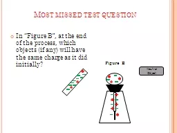
/
In “Figure B”, at the end of the process, which objects (if any) will have the same In “Figure B”, at the end of the process, which objects (if any) will have the same

In “Figure B”, at the end of the process, which objects (if any) will have the same - PowerPoint Presentation

danika-pritchard
danika-pritchard . @danika-pritchard
Follow
349 views
Uploaded On 2018-11-01

In “Figure B”, at the end of the process, which objects (if any) will have the same - PPT Presentation

Neutral Object Figure B Most missed test question Most missed test question If switch 2 and 4 are open and all other switches are closed which devices will be on Name Period ID: 707256

field magnetic wire current magnetic field current wire voltage transformer direction loop magnets coil turns secondary power hand primary

Share:

Link:

Embed:

Download Presentation from below link

Download Presentation The PPT/PDF document "In “Figure B”, at the end of the pro..." is the property of its rightful owner. Permission is granted to download and print the materials on this web site for personal, non-commercial use only, and to display it on your personal computer provided you do not modify the materials and that you retain all copyright notices contained in the materials. By downloading content from our website, you accept the terms of this agreement.


Presentation Transcript

Slide1

In “Figure B”, at the end of the process, which objects (if any) will have the same charge as it did initially?

Neutral Object

Figure B

Most missed test question

Slide2

Most missed test question

If switch 2 and 4 are open and all other switches are closed, which

device(s

) will be on?Slide3

Name

Period

Test Corrections: Ch. 20-23 A or B

Please take out a blank sheet of notebook paper and label it as shown aboveSlide4

Copy each question you missed. You do not have to copy the graphs, but you are welcome to do so if you like.

Do

not copy the answers choices unless you want to work on this at home.

If a problem required you to do work, you must show it on paper

or reference your scratch paper.

Write the answer choice and put a box around it. Ex. A. 300.0J

6-B21-C

23-A31-D

Name

Period

Test Corrections: Ch. 20-23 A or B

Use your

scantron

to make a list of every question you missed and the answer choice you made.Slide5

Journal #60 2/10/11

(Look

your progress report onto your journal page and write a reflection on your current grade and any changes you need to make in order to do better in this class)

Example:My daily grade is my worst grade. I need to be better prepared for my HW assignments and probably need to come in for tutorials at least once a week. My test grades are strong, but I think I can still improve by taking my time and double checking my work. After looking at my test corrections, it seems that vocabulary is a bigger issue than the math stuff.Slide6

Electromagnetism

Ch. 24-25

Quiz – Formulas and Vocabulary – Friday, Feb 18

Test – Ch. 24-25 – Tuesday, March 1Slide7

Magnets

Magnets have been around for more than two thousand years

One of the earliest uses for magnets was in navigation by using compasses

Other uses include electric motors, generators, television sets,

computer hard drives, and high speed trainsSlide8

Bar Magnets

The north and south side represent to two poles of the bar magnet

Bar magnets are examples of permanent magnetsAll magnets are

polarized, which mean they have two distinct and opposite ends.

Opposite poles attract; Similar poles repel. Why?Slide9

Magnetic Fields

The reason magnets attract and repel each other are due to the magnetic fields around them

Every magnet has a magnetic field around it

Magnetic field lines are similar to electric field lines

Field lines start at the north pole and end at the south poleMagnetic field strength has units of Teslas (T)Slide10

Magnetic Domains

What happens if you break a magnet in half?The two halves will still be polarized!!!

A domain is a group of neighboring atoms that have the magnetic fields of their electrons aligned in the same direction.

Magnetic materials have their domains aligned in the same direction, while non-magnetic materials have domains in random directions!

Non-magneticMagneticSlide11

Electromagnetism

Electromagnetism describes the relationship between electricity and magnetism.We use electromagnets to generate electricity, store memory on our computers, generate pictures on a television screen, diagnose illnesses, and in just about every other aspect of our lives that depends on electricity.

Electromagnetism works on the principle that an electric current through a wire generates a magnetic field.Slide12

Electromagnets

When DC electricity is passed through a wire, a magnetic field rotates around the wire in a specific direction.

“Right Hand Rule”-If you take your right hand and wrap it around the wire, with your thumb pointing in the direction of the electrical current (positive to negative), then your fingers are pointing in the direction of the magnetic field around the wire.Slide13

Solenoids

How would we model the magnetic field in a current loop?

A solenoid is a long coil of wire consisting of many loops.

The more loops a solenoid has, the stronger the magnetic field.Slide14

Magnetism Conventions

Current:Current is represented by the letter

ILeft, right, up, and down are drawn by arrows

Into the page or away from you is represented by Out of the page or towards you is represented by

Magnetic Field:Clockwise and counter-clockwise are drawn by arrowsInto the page or away from you is represented byOut of the page or towards you is represented bySlide15

Right Hand Rule Practice

Use the right hand rule to draw the magnetic field around the wire shown below

I

Current to the right

Magnetic field towards you above the wire and away from you below the wireSlide16

Right Hand Rule Practice

Use the right hand rule to draw the magnetic field around the wires shown below

I

I

Current out of the page

Counterclockwise magnetic field

Current into the page

Clockwise magnetic fieldSlide17

Right Hand Rule Practice

Use the right hand rule to draw the magnetic field through the wire loops as shown below

I

Current clockwise

Magnetic field towards you outside the loop and away from you inside the loop

Current to the right (

ccw

)

Magnetic field points upward through the loop and downward outside the loopSlide18

Journal #61 2/11/11

Draw the field around the following 3 wires:

I

A)

B)

C)

I

ISlide19

Electromagnets

This magnetic field is the same force that makes metal objects stick to permanent magnets. In a bar magnet, the magnetic field runs from the north to the south pole.

In a wire, the magnetic field forms around the wire. If we wrap that wire around a metal object, we can often magnetize that object. In this way, we can create an electromagnet.Slide20

Galvanometers

A galvanometer is a device used to measure very small amounts of current ( ~50 x 10

-6 A)The current through the wire loop creates a magnetic field

The interaction between the loop’s magnetic field and the permanent magnetic field causes the loop to rotate.Slide21

Electromagnetic Induction

When a wire moves in a magnetic field, a force acts on the charges in the wire. Work is done on the charges, causing the electrons to move.

Magnetic fields can induce a current in a wire!

For EM induction to occur, the wire or the magnetic field needs to be moving or changing in strength.Slide22

DC MotorsSlide23

What is the function of the Split-ring Commutator?

If you look closely, you will see that it switches the flow of current half-way through the rotation of the armature.

By doing so, it reverses the magnetic field produced around the armature. This reversal at the exact right moment makes the armature continue to be pushed/pulled by the forces of the magnets.

The armature is a wire loop mounted on an axle (it can be a single loop, or many repetitive loops).Slide24

Pre-Lab: Electric Motors

Purpose of Lab:Create a functional motor and modify it’s components to change it’s ability.

Today you will write down the function of each piece of equipment so that you don’t have to ask questions about

them tomorrow.Slide25

Equipment

4 D-cell batteries provide potential difference to the circuit containing the electromagnet

The electromagnet has a sensor on the end that detects dark or clear and reverses the current alternating it’s polarity

The commutator discs have different numbers of alternating clear/black edges

The magnets must be arranged in the rotor in a specific pattern in order for the electromagnet to effectively “push and pull” it continuously

The rotor is freely spinning on ball bearings, but the commutator discs must be firmly attached with the washer so that they don’t shift

A

photogate

will be placed in this position so that it can measure the frequency of color changes. That information will be used to calculate the rotational speed of the disc/motorSlide26

Electric Generators

The electric generator was invented by Michael Faraday and converts mechanical energy into electrical energy.

The armature is often wrapped around an iron core.The armature is free to rotate in the magnetic field. As the wire rotates in the magnetic field, a current is induced.

As the loop rotates, the strength and direction of the current change, producing an alternating current.Slide27

Difference in AC/DC Current

The difference between AC and DC has to do with the direction in which the electrons flow. In DC, the electrons flow steadily in a single direction, or "forward."

In AC, electrons keep switching directions, sometimes going "forward" and then going "backward.”

In the US, electric utilities use a 60-Hz frequency, meaning that the current alternates direction (forward to backward and back to forward) 60 times in one second.Slide28

Transformers

The primary voltage (on the left) induces a magnetic field in the core, which creates the secondary voltage (on the right).

What makes transformers so useful is that if you change the number of turns

from one side to the other, you change the voltage in the wire on the right!

Transformers can change a high voltage to a lower one, or a low voltage to a higher one.Slide29

Step Up Transformer

A step-up transformer converts a low voltage to a higher one.

If you increase the number of turns on the right, the voltage coming off the transformer will increase in proportion.

The right side has 4 times more turns so the voltage on the right has increased 4 times.So the voltage has been stepped up by a factor of 4. Slide30

Step Down Transformer

Step-down transformer reduces voltage.

If you decrease the number of turns on the right, the voltage coming off the transformer will decrease in proportion.The right side has 1/5 the number of turns, so the voltage is only 1/5 as large.

So the voltage has been stepped down by 5. Slide31

Transformer Math

The ratio of the number of turns is the same as the ratio of the voltages

An ideal transformer, which we will always assume, dissipates no power (waste heat). The power of the primary circuit is equal to the power of the secondary current

We use this assumption about power to find the current in the secondary circuitSlide32

Final Thoughts on Transformers

Step-Up

Transformer

Step-

Down TransformerVp < Vs Vp > VsIp > Is

Ip < IsNp < Ns Np < NsSlide33

Why Transmit with AC vs. DC

Advantages to using AC:Transformers can only work using AC

b/c the magnetic field has to be constantly changing in order to induce the secondary current. Due to the constant change of direction of the electrons in AC, the magnetic field is always changing as well.

By using a step-up transformer to hike the voltage, we are able to lower the current and by lowering current, we are able to use thinner wires.

Ultimately, we are able to transfer power farther (higher voltage travels farther), for less money (cost of wire), with better efficiency (less power lost to heat caused by resistance).Slide34

Journal #62 February 14, 2010

The primary coil on a transformer has 100 turns and the secondary coil has 500 turns. The primary voltage is 110V and the current is 1.5 A.

What type of transformer is this?

What power is being used on the primary coil?

What are the resulting voltage and current in the secondary coil?What is the resulting power on the secondary coil?Slide35

Journal #63 February 16, 2010

The ratio of turns on a transformer is 100 on the primary to 1 on the secondary coil. The primary voltage is 12000V.

What type of transformer is this?

If the resistance on the secondary coil is 100-ohms, what current is induced on the coil?

If we consider this to be an ideal transformer, what power is being used on the primary coil? How do you know?