/
phone  www phone  www

phone www - PDF document

danika-pritchard
danika-pritchard . @danika-pritchard
Follow
372 views
Uploaded On 2014-11-12

phone www - PPT Presentation

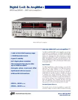
thinkSRScom Stanford Research Systems 57527 1 mHz to 1024 kHz frequency range 57527 100 dB dynamic reserve 57527 5 ppm57520C stability 57527 001 degree phase resolution 57527 Time constants from 10 ID: 10998

thinkSRScom Stanford Research Systems 57527

Share:

Link:

Embed:

Download Presentation from below link

Download Pdf The PPT/PDF document "phone www" is the property of its rightful owner. Permission is granted to download and print the materials on this web site for personal, non-commercial use only, and to display it on your personal computer provided you do not modify the materials and that you retain all copyright notices contained in the materials. By downloading content from our website, you accept the terms of this agreement.


Presentation Transcript

· 1 mHz to 102.4 kHz frequency range · �100 dB dynamic reserve · 5 ppm/°C stability · 0.01 degree phase resolution µs to 30 ks (up to 24 dB/oct rolloff) · Auto-gain, -phase, -reserve and -offset · Synthesized reference source · GPIB and RS-232 interfaces · SR810 ... $4150 (U.S. list) · SR830 ... $4950 (U.S. list) The SR810 and SR830 DSP Lock-In Amplifiers provide high performance at a reasonable cost. The SR830 simultaneously displays the magnitude and phase of a signal, while the SR810 displays the magnitude only. Both instruments use digital signal processing (DSP) to replace the demodulators, output filters, and amplifiers found in conventional lock-ins. The SR810 and SR830 provide uncompromised performance with an operating range of 1 mHz to 102 kHz and 100 dB of drift- Input Channel The SR810 and SR830 have differential inputs with 6 nV/√Hz input noise. The input impedance is 10 MΩ, and minimum full-scale input voltage sensitivity is 2 nV. The inputs can current gains of 10 6 and 10 8 V/A. A line filter (50 Hz or 60 Hz) and a 2× line filter (100 Hz or 120 Hz) are provided to eliminate line related interference. However, unlike conventional lock-in amplifiers, no tracking band-pass filter is needed at the input. This filter is used by conventional lock- filters also introduce noise, amplitude and phase error, and drift. The DSP design of these lock-ins has such inherently large dynamic reserve that no band pass filter is needed. Extended Dynamic Reserve The dynamic reserve of a lock-in amplifier, at a given full- scale input voltage, is the ratio (in dB) of the largest interfering phone: (408)744-9040 www.thinkSRS.com Stanford Research Systems SR810 & SR830 DSP Lock-In Amplifiers Digital Lock-In Amplifiers SR810 and SR830 — DSP lock-in amplifiers SR830 DSP Lock-In Amplifier SR810 and SR830 DSP Lock-In Amplifiers signal to the full-scale input voltage. The largest interfering signal is defined as the amplitude of the largest signal at any frequency that can be applied to the input before the lock-in cannot measure a signal with its specified accuracy. Conventional lock-in amplifiers use an analog demodulator to mix an input signal with a reference signal. Dynamic reserve is limited to about 60 dB, and these instruments suffer from poor stability, output drift, and excessive gain and phase error. Demodulation in the SR810 and SR830 is accomplished by sampling the input signal with a high-precision A/D converter, and multiplying the digitized input by a synthesized reference signal. This digital demodulation technique results in more than 100 dB of true dynamic reserve (no prefiltering) and is free of the errors associated with analog instruments. Digital Filtering The digital signal processor also handles the task of output filtering, allowing time constants from 10 µs to 30,000 s with a choice of 6, 12, 18 and 24 dB/oct rolloff. For low frequency measurements (below 200 Hz), synchronous filters can be engaged to notch out multiples of the reference frequency. Since the harmonics of the reference have been eliminated (notably 2F), effective output filtering can be achieved with much shorter time constants. Digital Phase Shifting Analog phase shifting circuits have also been replaced with a DSP calculation. Phase is measured with 0.01° resolution, and the X and Y outputs are orthogonal to 0.001°. Frequency Synthesizer The built-in direct digital synthesis (DDS) source generates dBc) reference signal. Single frequency sine waves can be generated from 1 mHz to 102 kHz with 4½ digits of resolution. Both frequency and amplitude can be set from the front panel or from a computer. When using an external reference, the synthesized source is phase locked to the reference signal. Useful Features Auto-functions allow parameters that are frequently adjusted to automatically be set by the instrument. Gain, phase, offset and dynamic reserve are quickly optimized with a single key press. The offset and expand features are useful when examining small fluctuations in a measurement. The input signal is quickly nulled with the auto-offset function, and resolution is increased by expanding around the relative value by up to 100×. Harmonic detection isn’t limited to 2F — any harmonic (2F, 3F, ... nF) up to 102 kHz can be measured. Analog Inputs and Outputs Both instruments have a user-defined output for measuring X, R, X-noise, Aux 1, Aux 2, or the ratio of the input signal to an external voltage. The SR830 has a second, user-defined output that measures Y, θ, Y-noise, Aux 3, Aux 4 or ratio. The SR810 and SR830 both have X and Y analog outputs (rear panel) that are updated at 256 kHz. Four auxiliary inputs (16-bit ADCs) are provided for general purpose use — like normalizing the input to source intensity fluctuations. Four programmable outputs (16-bit DACs) provide voltages from –10.5 V to +10.5 V and are settable via the front panel or computer interfaces. Internal Memory The SR810 has an 8,000 point memory buffer for recording the time history of a measurement at rates up to 512 samples/s. The SR830 has two, 16k point buffers to simultaneously record two measurements. Data is transferred from the buffers using the computer interfaces. A trigger input is also provided to externally synchronize data recording. Easy Operation The SR810 and SR830 are simple to use. All functions are set from the front-panel keypad, and a spin knob is provided to quickly adjust parameters. Up to nine different instrument configurations can be stored in non-volatile RAM for fast and easy instrument setup. Standard RS-232 and GPIB (IEEE- 488.2) interfaces allow communication with computers. Ordering Information SR830 DSP dual phase lock-in $4950 amplifier SR810 DSP single phase lock-in $4150 amplifier Voltage preamplifier (100 MΩ, 3.6 nV/√Hz) Voltage preamplifier (100 kΩ, 1.4 nV/√Hz) Transformer preamplifier (0.091 nV/√Hz) Current preamplifier Current preamplifier Optical chopper SR810 DSP Single Phase Lock-In Amplifier SR810/830 rear panel SR810 and SR830 Specifications Signal Channel Voltage inputsSingle-ended or differential Sensitivity2 nV to 1 V Current input10 6 or 10 8 V/A Input impedance 10 + 25 pF, AC or DC coupled 1 kΩ to virtual ground Gain accuracy % (±0.2 % typ.) Noise (typ.)6 nV/√Hz at 1 kHz 0.13 pA/√Hz at 1 kHz (10 6 V/A) 0.013 pA/√Hz at 100 Hz (10 8 V/A) Line filters Hz and 100/120 Hz (Q = 4 ) CMRR dB to 10 kHz, decreasing by 6 dB/oct above 10 kHz Dynamic reserve dB (without prefilters) Stability ppm/°C Reference Channel Frequency range0.001 Hz to 102.4 kHz Reference inputTTL or sine (400 mVpp min.) Input impedance1 MΩ, 25 pF 0.01° front panel, 0.008° through computer interfaces Absolute phase error° Relative phase error Orthogonality90° ± 0.001° Phase noise Internal ref.Synthesized, ° kHz External ref. kHz (100 ms time constant, 12 dB/oct) Phase drift°° kHz, kHz Harmonic detection 2F, 3F, ... nF to 102 kHz (n ) Acquisition time + 5 ms) or 40 ms, Demodulator Digital outputs and display: no drift ppm/°C for all dynamic reserve settings Harmonic rejection dB Time constants µs to 30 ks (6, 12, 18, 24 dB/oct available below 200 Hz. Internal Oscillator Range mHz to 102 kHz Frequency accuracy25 ppm + 30 µHz Frequency resolution4½ digits or 0.1 Distortion dBc (f 10 kHz), –70 dBc (f � 10 kHz) @ 1 Vrms amplitude Amplitude0.004 to 5 Vrms into 10 kΩ (2 mV resolution), 50 Ω output impedance, 50 mA maximum current into 50 Amplitude accuracy % Amplitude stability ppm/°C OutputsSine, TTL (When using an external reference, both outputs are phase locked to the external reference.) Displays Channel 14½-digit LED display with 40-segment LED bar graph. X, R, quantities divided by Aux 1 or Aux 2. Channel 2 (SR830) 4½-digit LED display with 40-segment LED bar graph. Y, θ , Y-noise, Aux 3 or Aux 4. The display OffsetX, Y, R can be offset up to ±105 % X, Y, R can be expanded by 10× 4½-digit LED display Inputs and Outputs (±10 V), updated at 512 Hz. CH2 output (SR830)Y, θ, Y-noise, Aux 3 or Aux 4 (±10 V), updated at 512 Hz. X, Y outputs In-phase and quadrature components (rear panel)(±10 V), updated at 256 kHz Aux. A/D inputs4 BNC inputs, 16-bit, ±10 V, 1 mV resolution, sampled at 512 Hz Aux. D/A outputs4 BNC outputs, 16-bit, ±10 V, 1 mV resolution Internal oscillator analog output TTL outInternal oscillator TTL output Data bufferThe SR810 has an 8k point buffer. 512 Hz and read through the computer interfaces. Trigger in (TTL)Trigger synchronizes data recording Remote preamp General Interfaces Power W, 100/120/220/240 VAC, 50/60 Hz Dimensions " × 5.25 " × 19.5 " (WHD) Weight23 lbs. WarrantyOne year parts and labor on defects in materials and workmanship Stanford Research Systems phone: (408)744-9040 www.thinkSRS.com