/
U.S. DOE Perspective on Lithium-ion Battery Safety U.S. DOE Perspective on Lithium-ion Battery Safety

U.S. DOE Perspective on Lithium-ion Battery Safety - PowerPoint Presentation

danika-pritchard
danika-pritchard . @danika-pritchard
Follow
454 views
Uploaded On 2016-05-24

U.S. DOE Perspective on Lithium-ion Battery Safety - PPT Presentation

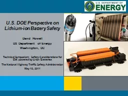
David Howell US Department of Energy Washington DC Technical Symposium Safety Considerations for EVs powered by Liion Batteries The National Highway Traffic Safety Administration May 18 2011 ID: 332892

safety battery thermal cell battery safety cell thermal abuse testing pack amp vehicle design energy doe development batteries develop

Share:

Link:

Embed:

Download Presentation from below link

Download Presentation The PPT/PDF document "U.S. DOE Perspective on Lithium-ion Batt..." is the property of its rightful owner. Permission is granted to download and print the materials on this web site for personal, non-commercial use only, and to display it on your personal computer provided you do not modify the materials and that you retain all copyright notices contained in the materials. By downloading content from our website, you accept the terms of this agreement.


Presentation Transcript

Slide1

U.S. DOE Perspective on Lithium-ion Battery SafetyDavid HowellUS Department of EnergyWashington, DC Technical Symposium: Safety Considerations for EVs powered by Li-ion BatteriesThe National Highway Traffic Safety AdministrationMay 18, 2011Slide2

Outline

Program Overview

Safety and Abuse Tolerance Activities

DOE Safety/Abuse Testing

Battery Design & Modeling

Materials R&D

Vehicle Testing

Collaborations

Summary & DOE PerspectivesSlide3

CathodeAl Current CollectorAnodeCu Current Collector

e

e

e

Separator

Li

+

Programmatic Structure

New Materials

Research

Diagnostics & Modeling

Standardized

Testing

Life Projections

Design

Tools

Next Generation Cell Development

Performance &

Cost Reduction

Electrochemistry Optimization

Power & Capacity

Life, Improvement

MISSION:

Advance the development of batteries to enable a large market

penetration

of hybrid and electric

vehicles to achieve large national benefits..

3

| Energy Efficiency and Renewable EnergySlide4

Major Technical Challenges and BarriersCostSpecific Energy/Energy DensitySafetyBarrier/ChallengePotential Solutions

Reduce Cost

Improve material and cell durabilityImprove energy density of active materials

Improved manufacturing processes

Improved design tools/design optimization

Significantly Increase Energy Density

(3

rd

generation lithium-ion, lithium-sulfur, lithium-air)

Develop ceramic, polymer, and hybrid structures with high conductivity, low impedance, and structural stability

Select improved electrolyte/separator combinations to reduce

dendrite growth

Improve Abuse Tolerance

(High energy density, reactive materials, flammable electrolytes)

Implement battery cell and pack level innovations (e.g., improved sensing, monitoring, and thermal management systems)

Implement b

attery materials innovations (e.g., non-flammable electrolytes, high-temperature

melt integrity separators, additives & coatings)

4

| Energy Efficiency and Renewable EnergySlide5

Battery Cell Form Factors5 | Energy Efficiency and Renewable Energy

Battery Pack with Cylindrical Cells

Battery Pack with Prismatic Cells

Courtesy: Johnson Controls Inc.

Courtesy: A123Systems Slide6

Safety/Abuse Tolerance TestingAbusive ConditionsMechanical (crush, penetration, shock)Electrical (short circuit, overcharge, over discharge)Thermal (overheating from external/internal sources)Abuse Testing MethodologySAE Abuse Test Manual J2464Several members of the VTP Team participated on the committee to develop the new SAE Abuse Test ManualFacilities

: Sandia National Laboratories was awarded funding through the American Reinvestment and Recovery Act (ARRA) for facility upgrades to the Battery Abuse Testing Laboratory. Improving the safety engineering controls and systems required to accommodate abuse testing PHEV and EV sized batteries,

Updating laboratory equipment and systems to facilitate the growing demand for safety testing.

CT image of an 18650

Li-

ion cell with a large defect in the

rollSlide7

Many field failures are caused by internal shorts resulting from manufacturing defects or foreign particles inadvertently incorporated in the cell during manufacture.The internal short could lead to thermal runaway and severe reactions.DOE has funded multiple projects to develop techniques to mimic internal shorts on demand.The purpose of the work is to develop a tool or technique that will be used to develop methods to detect and mitigate internal shorts.Techniques under development includeLow-melting point metal alloys used to trigger ISCs at relatively low temperatures (SNL and NREL)

Pinch test using spherical balls (ORNL)Proprietary method (TIAX)

Preliminary experimental demonstration of differences in ISC severity based on short type (current collector-current collector, current collector-active material)Experimental data will be incorporated in thermal models developed by

NREL and TIAX. Reproducibility needs to improve for all methods

Test Methods Development

“On Demand” Internal Short

Circuit Test Development Slide8

ARC profiles plotted as heating rate as a function of temperature for the fresh cell (in blue) and 20% faded aged cell (in green) populations. Accelerating Rate Calorimetry (ARC)

Impact of Cell Age on Abuse Response

Aged Cell TestingSlide9

Battery Development Efforts to Improve Safety

The United States Advanced Battery Consortium (USABC) is a collaborative effort among Ford, GM, Chrysler and DOE to develop advanced automotive batteries.

Abuse tolerance is among the barriers being addressed. The cell materials technologies being developed are:

Safety reinforced separatorsCeramic filled separatorsHigh temperature melt integrity separators

Coatings on high voltage cathodesCathode additives to improve abuseElectrolyte additives to mitigate overcharge

Heat resistant layers on anode and cathode electrodes

United States Advanced Battery Consortium (USABC

)

AlF

3

coating layer for cathodesSlide10

Work

at cell & pack

level also includes improving abuse tolerance.Technologies being developed:Charge interrupt devices Cell vent designs to release electrolyte gasses prior to thermal runaway

System designs that manage vented gasses away from passenger areasLiquid and gas, active and passive, thermal management systemsSimulations to evaluate abuse tolerance mitigation technologies at the cell and system

level

USABC Cell and Abuse Tolerance Improvement Efforts

Schematic of Prismatic Cell

Cathode pin

Top cover

Insulator case

Spring plate

Anode can

Anode

Cathode

Separator

Cathode lead

Safety vent

Gasket

Insulator

Terminal plate

CID

Wound or Stacked Electrodes

Battery Development Efforts to Improve SafetySlide11

Battery Design & Modeling

Computer-aided Engineering of Batteries (CAEBAT)

Develop computer-aided

engineering (CAE) tools for the design and development of battery systems for electric drive vehicles

Develop and incorporate

existing and new models into a battery design

suite to reduce battery development time and cost while improving safety and performance

Include CAE

tools to predict and improve safety of cells and

battery

packs

Battery

design suite must address multi-scale physics interactions, be flexible, expandable, and validated

Element

4: Open Architecture Software

CAEBAT Overall Program

Element 1

Component

Level Models

Element 3

Battery Pack

Level Models

Element 2

Cell

Level ModelsSlide12

Battery Safety Abuse ModelingThermal Response and Short Circuit ModelingEC-Power : thermal response, full and partial nail penetration, s

horting by metal

particleNREL , Tiax

: thermal response, and internal short circuit models

Structural Crash Models

University of Michigan (USCAR funding) developing

a mechanical constitutive analytical model and a numerical simulation model.

Sandia National Labs (DOE funding)

validating the models

Future R&D to develop safety modeling that combines electrochemical-thermal coupled models with mechanical material models.

0.5s

10s

100s

Diameter = 0.5 mm

T

max

=180

o

C

T

avg

= 34

o

C

T

max

-T

avg

=146

o

C

T

max

=58

o

C

T

avg

= 53

o

C

T

max

-T

avg

=5

o

C

T

max

=116

o

C

T

avg

= 113

o

C

T

max

-T

avg

=3

o

C

Diameter = 8 mm

0.5s

10s

100s

T

max

=36

o

C

T

avg

= 34

o

C

T

max

-T

avg

=2

o

C

T

max

=52.8

o

C

T

avg

= 52.3

o

C

T

max

-T

avg

=0.5

o

C

T

max

=114

o

C

T

avg

= 112

o

C

T

max

-T

avg

=2

o

C

Full PenetrationSlide13

Increased thermal-runaway-temperature and reduced peak-heating-rate for full cellsDecreased cathode reactions associated with decreasing oxygen releaseEC:PC:DMC1.2M LiPF6Accelerating Rate

Calorimetry (ARC)

Materials R&D

Cathodes with Improved StabilitySlide14

Cathode coatings and novel electrolytes

AlF

3

-coating improves the thermal stability of NMC materials by 20°C

Improves thermal response during cell runaway

Thermal Response of AlF

3

-coated Gen3 cathode in 18650 cells by ARC

Materials R&D (cont’d)

50% reduction in total heat output of NMC 433 with

LiF

/ABA

electrolyte compared to standard electrolyte,

Reduce gas generation and decomposition

products

Anion Boron Receptor ElectrolyteSlide15

DOE’s Advanced Vehicle Testing Activity tests and collects data on electric drive vehicles (EDVs) using conversion, prototype, and production vehicles, some with Li-ion batteries. In 2011, data was collected for 6,500 vehicles over trips covering more than 26 million miles in EDVs with almost no adverse events. Three thermal events have occurred in non-production vehicles in recent years.

DOE Fleet Testing Safety ExperienceSlide16

DOE Fleet Testing Safety Experience Vehicle 1Vehicle 2Vehicle 3TypeHEV converted into a PHEV by adding a 12 kWh Li-ion packHEV converted into a PHEV : NiMH pack with a 5kWh Li-ion packPHEV with a 12kWh packEventBattery received 13.5kWh overchargeSignificant smoke, heat,

but no flame evidenceBattery cells remained in place

Components (pouch bag, solvents, separator) with low melting points were missingVehicle fireConverter design deviated from battery manufacturer design guidelines

The first responders had easy access to the battery, significant damage occurred to the pack and the vehicle before they arrived

Significant smoke, heat, but no flame evidence

The first responders sprayed significant volumes of water into the vehicle to extinguish the melting seat and carpeting

Pack resumed smoking and significant heat rise. Testing indicated one module had high voltage

Load bank was used to discharge the high voltage module

and stabilize battery.

Cause

Likely a faulty charger or BMS

Likely caused by improper assembly of bolted joints with electric lugs

Most likely cause of the failure was faulty wiring design.Slide17

Damage can be limited if responders have good access to the battery packFull battery discharge/thermal event can continue over multiple daysIssues to consider with PHEV battery and vehicle designLack of common disconnect locations Responders unaware of hazardsElectrical safety personal protection equipment (PPE) and breathing apparatus should be worn by first responders

Access to battery pack is critical IF

an event occursDOE Fleet Testing Safety Experience

SummarySlide18

Intra Government Collaborations

DOT/NHTSA

Technical support for Regulations for battery transportationCollaboration on Battery Safety tests with NHTSA and NSWC

DOE/DOT/INL is working with the National Fire Prevention Association to develop PPE needs and first responder training aids. We are filming multiple lithium battery test burns with multiple suppression methods utilizedJoint

studies, working groups

Volt battery pack being prepared for testSlide19

DOE Perspective Regarding Lithium-ion Battery Safety

Safety is a key barrier to introduction of rechargeable batteries into vehicles.

Vehicle environment is challenging (temperature, vibration, etc.)

Large cells and large capacity batteries for vehicle traction present additional challenges

Safety is a systems issue, with many inputs and factors.

Even “safe” cells and batteries can prove unsafe in some applications due to poor engineering implementation or an incomplete understanding of system interactions.

Standardized tests are crucial to obtain a fair comparison of different technologies and to gauge improvements

.

Safety of Batteries is of Central Importance