PPT-Use of Bessel Function in Designing Fiber
Author : danika-pritchard | Published Date : 2018-09-21
for Fiber Optic Communication Michael Ghoorchian Fiber Optic An optical fiber is a glass or plastic fiber that carries light along its length so it acts as a
Presentation Embed Code
Download Presentation
Download Presentation The PPT/PDF document "Use of Bessel Function in Designing Fib..." is the property of its rightful owner. Permission is granted to download and print the materials on this website for personal, non-commercial use only, and to display it on your personal computer provided you do not modify the materials and that you retain all copyright notices contained in the materials. By downloading content from our website, you accept the terms of this agreement.
Use of Bessel Function in Designing Fiber: Transcript
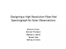
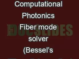
for Fiber Optic Communication Michael Ghoorchian Fiber Optic An optical fiber is a glass or plastic fiber that carries light along its length so it acts as a Wave guide Mostly made of Silicon not Silicone . we have that is a second solution of the di64256erential equation 2 and the two solutions and are clearly linearly independent For 8712 we have 0 1 915 1 1 915 1 since 915 1 0 for 0 n This implies that 1 915 1 0 1 915 1 2 1 0 1 91 02 501 V 75V V IN 2V RMS Operates with a Single 5V Supply 1V RMS Input Range 60 RMS Clock Feedthrough Single 5V Supply Operates up to 8V Supplies TTLCMOSCompatible Clock Input No External Components Available in 14Pin DIP and 16Pin SO Wide Packages 02 501 V 75V V IN 2V RMS Operates with a Single 5V Supply 1V RMS Input Range 60 RMS Clock Feedthrough Single 5V Supply Operates up to 8V Supplies TTLCMOSCompatible Clock Input No External Components Available in 14Pin DIP and 16Pin SO Wide Packages Infrastructure. Dr. . Natheer. . Khasawneh. Rafat A. Dasan. This chapter will cover…. DC's . structured cabling and outline the importance of a well-organized physical hierarchy. .. Explain . the differences between common cabling media, suggests which are most appropriate in various scenarios, and presents best practices for installation and testing.. Benefits of Fiber Fiber not only promotes health, it also help reduce the risk for some chronic diseases. For instance, fiber prevents constipation , hemorrhoids and diverticulosis. Fiber is also li Edmond Wilson. Brennan Thomason. Stephanie Inabnet. Tamara Reed. Harding University. Project Goal. Design a spreadsheet program to aid in optimizing the light throughput of a Czerny-Turner Spectrograph fed by an optical fiber. Fins. extended surfaces that enhance fluid heat transfer to/from a surface in large part by increasing the . effective surface area . of the body. combine . conduction through the fin. and . convection to/from the fin. Co-Authors: Joshua Nelson, Adam Summers, Dr. Carlos Trallero and Dr. Bret Flanders. Axicon Project. Increase efficiency of power transmission through a hollow core fiber. Propagation through fiber reduces output power. Why Fiber?. Unlimited. . Capacity. . Single Fiber Pair. Special Construction on lit fiber service . Service provider owned. Upfront capital to reduce monthly recurring costs . General Industry Definitions:. Seminar . 06. Learn how to . combine analytical solutions with numerical routines to find semi-analytical solutions. Use your lecture knowledge to specify the general cylindrical problem . solution to a step-index fiber. strengths-based . questions . September 2018. Before you start…. To ensure that you understand this new method of assessing . candidates, please . make sure you have completed the . Success Profiles . Design COP 3538 Summer 2012 © Lethbridge/Laganière 2001 Chapter 9: Architecting and designing software 2 The Process of Design Definition: Design is a problem-solving process whose objective is to find and describe a way: Fiber is also known as bulk or roughage.. It helps promote digestion of food, as well as elimination of . waste . from the body. What are the Two Types of Fiber?. Soluble Fiber:. - Is only partially digested within the body. Dmitriy. . Churin. Course OPTI-521. 1. Overview. What is a single frequency laser . Applications of single frequency lasers. Identifying the limitation of the fiber single frequency lasers. Stimulated .
Download Document
Here is the link to download the presentation.
"Use of Bessel Function in Designing Fiber"The content belongs to its owner. You may download and print it for personal use, without modification, and keep all copyright notices. By downloading, you agree to these terms.
Related Documents