/
r Commercial Applications Greg Barker, Mountain Energy Partnership Jam r Commercial Applications Greg Barker, Mountain Energy Partnership Jam

r Commercial Applications Greg Barker, Mountain Energy Partnership Jam - PDF document

debby-jeon
debby-jeon . @debby-jeon
Follow
450 views
Uploaded On 2015-11-19

r Commercial Applications Greg Barker, Mountain Energy Partnership Jam - PPT Presentation

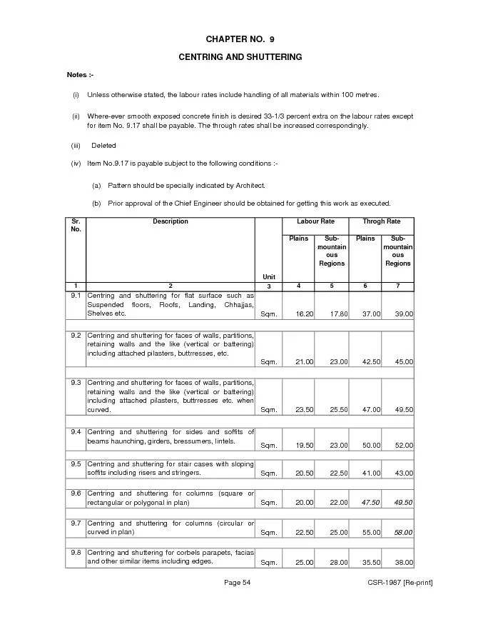
The economics of such collectors depend on installation solar resource and sizing BTUs delivered per square Figure 1 shows original designs which achieved 70 efficiency at 6 FPM and higher accord ID: 198407

The economics such collectors

Share:

Link:

Embed:

Download Presentation from below link

Download Pdf The PPT/PDF document "r Commercial Applications Greg Barker, M..." is the property of its rightful owner. Permission is granted to download and print the materials on this web site for personal, non-commercial use only, and to display it on your personal computer provided you do not modify the materials and that you retain all copyright notices contained in the materials. By downloading content from our website, you accept the terms of this agreement.


Presentation Transcript

r Commercial Applications Greg Barker, Mountain Energy Partnership James McClendon, Wal-Mart ABSTRACT Using transpired solar collectors to preheat ventilation air has recently become recognized as an economic alteble energy into commercial buildings in heating climates. The collectors have relatively low installed costs and operate on simple principles. Theory and performance testing have shown that solar collection efficiency can exceed 70% of incident solar. However, implementation and current absorber designs have adversely affected the efficiency and associated economics from this initial analysis. The National Renewable Energy Laboratory (NREL) has actively studied this technology and monitored performance at several installations. A calibrated model that uses typical meteorological weather data to determine absorber plate efficiency resulted from this work. With this model, an economic analysis across heating climates was done to show the effects of collector size, tilt, azimuth, and absorptivity. The analysis relates the internal rate of return of a system based on the cost of the installed absorber area. In general, colder and higher latitude climates return a higher rate of return because the heating season extends into months with good Wal-Mart has installed approximately 8,000 ft of absorber at its experimental store in Aurora, Colorado. The delivered energy efficiency was measured at 8-11% during January and February 2007. The low collection efficiency is largely due to the oversized absorber and to the multizone control strategy that limits the amount of air pulled through the collector. Analysis shows that more than 50% of the incident solar energy could be delivered with proper control Background Transpired Solar Collectors Transpired solar collectors are an emerging solar technology. The collector consists of a porous absorber plate with associated plenum and ducting. The absorber is mounted to collect sunlight and outdoor air is actively drawn through the porous plate. The air is heated as it transpires (perpendicularly) through the plate. The air is then collected in a plenum on the back side of the plate and delivered to the building. A transpired collector traditionally serves two Collect solar heat and transfer it to a ventilation air flow by virtue of air transpiration Perform all the normal functions of a building’s façade on which it is installed. The economics of such collectors depend on installation, solar resource, and sizing (BTUs delivered per square Figure 1 shows original designs which achieved 70%+ efficiency at 6 FPM and higher according to Kutscher et al. (1993). However, current designs are closer to 60%+ efficiency at the same flow rate. This results in an air temperature increase of about 36F on a typical sunny day with a transpired collector facing due south. Increasing wall area (and thus lowering the approach velocity) can increase the total energy harvested, but because collector efficiency can drop sharply, it has diminishing economic returns. Furthermore, wind losses become much more prevalent at low approach velocities. A selective low-e coating (with high solar absorptivity and low long wave radiation emissivity) can enable high efficiency at lower approach velocity; however, the practical aspects of cost, visual appearance, and maintenance are outside this Figure 1. Efficiency and Temperature RiFigure Taken from Kutscher et al. (1993), 0.01 m/s ≅ 2 FPM, 700 W/m Figure 2. Pressure Drop Measurements of Current South Wall Transpired Collector Products 024681012Face Velocity (FPM)Pressure Drop (Pa)0.000.080.160.240.320.000.010.020.030.040.050.060.07Face Velocity (m/sec)Pressure Drop (inches water) The induced pressure drop across the absorber plate should be sufficient to impede the effect of wind impingement, which could lead to air flow in and out of the absorber. To prevent this, the pressure drop should be greater than the wind’s dynamic pressure. For practical purposes, high winds and gusting do not coincide with large portion of collector operational hours, therefore, the highest expected mean wind speed is used. Eleven mph (5 m/s) is a typical high wind speed in the United States, which has a dynamic pressure of approximately 15 Pa. Typical pressure drop performance of current south wall-mounted products is shown in Figure 2. The pressure drop at 6 FPM face velocity is marginal; however, it meets our 15 Pa criteria. Ventilation accounts for about 15% of the net commercial buildings heating load in the United States (DOE 2006). This heating energy is normally met with fossil fuel energy sources. Ventilation heating can be economically augmented from renewable energy sources because low grade heat (such as that from a transpired collector) can be utilized. Low-grade solar heat is attractive because high efficiencies and low absorber costs are possible. However, air-to-air heat recovery should be examined as an option when the exhaust air stream from a building is readily available. The total year-round energy savings and economics of heat recovery will likely exceed those of a transpired solar collector according to prior NREL analysis. The following list illustrates the advantages of heat recovery over a transpired collector. Transpired collectors are most useful during sunny days during heating months. This would typically be about 6-10 hrs/day for 6-10 months or about 12-35% utilization over the year. The highest utilization is realized only in special cases such as when used to ventilate the refrigeration sHeat recovery can be used for nearly the entire year (cooling and heating), except when economizer cooling is more efficient. This would yield higher utilization than a transpired collector. Furthermore, a building’s total ventilation load may be the greatest during nighttime winter hours and humid summer days. Energy recovery can provide heating and cooling that can lead to downsized heating and cooling equipment. A transpired collector cannot downsize the heatequipment because of the non-coincident nature of solar resource and heating peak load. Since not all exhaust air is recoverable (e.g., kitchen exhaust and exfiltration), the preceding arguments suggest that a good application for a transpired solar collector is ventilation make-up air to supplement exhaust air heat recovery. Transpired Collector Model A new transpired collector model was developed at NREL in order to accurately model the performance of current collector products. The model has been calibrated to several installations that have been monitored by NREL. It uses hourly TMY2 data sets to accurately calculate the absorber’s performance and capture some dynamic details such as the effects of thermal mass. The NREL model predicts about 14% less delivered energy than the RETscreen (NRCan 2007) transpired collector model, which is based on product offerings that are no longer available. The following is a list of attributes of the model. The model uses hourly TMY2 weather data to incorporate solar insolation, ambient temperature, sky temperature, and wind speed into the wall’s overall heat balance and efficiency calculations. The model uses the above data along with thAir transpiration face velocity (FPM) Surface absorptivity and emissivity (both sides) Wall insulation Temperature of back wall (ambient or inside temperature, e.g., 70Specific heat and mass of the absorber plate and wall. The model takes all the inputs from 1 and 2, uses them to create a time-dependent energy balance, and calculates the air temperature increase from ambient to the delivered air. The model was calibrated using the methods by Kutscher et al. (1993) and data taken from an installation in New York. The calibration adjusts the coefficients used to approximate the absorber plate heat exchange effectiveness. As an approximation, building load is matched by modulating air flow from 100%, when the ambient temperature is below 55F ambient temperature. The transpired solar collector may be thought of as a new construction technology that is In the case of big box retail, the south wall of a building may be located a distance prohibitively far away from the end use, or may be unsuitable for solar energy harvesting. In this case, the concept of a modular transpired solar collector may make sense. A modular collector would be a roof mounted collector with integral ducting and be placed in proximity to the HVAC equipment. shows a prototype of such a unit. Commercial models are becoming available. According to NREL analysis, one advantage of a modular design is that the collector can be tilted from vertical to about latitude +10 to 20 to maximize energy harvesting. For Denver, Colorado, and most U.S. cities where a transpired collector is suitable, 60 is close to an optimal tilt. A notable exception is Seattle, Washington, where winter solar is poor, making a 50 tilt optimal. Northern climates such as Fairbanks, Alaska (latitude 65) also have an optimal tilt near 60 because of the lack of winter solar resource. However, spring, summer, and fall months ired collector viable. Figure 4 shows the ASHRAE (2004) climate zones in the United States. Select cities in each zone are used for benchmarking building technologies. Figure 4. Map of DOE Climate Zones Table 1. Climate Zone Locations of the Cities Selected for Modeling Locations Climate Zone Baltimore, MD 4A Albuquerque, NM 4B Seattle, WA 4C Chicago, IL 5A Boulder, CO 5B Minneapolis, MN 6A Helena, MT 6B Duluth, MN 7 Fairbanks, AK 8 The typical ventilation flow for a 200,000 ft retail store is approximately 35,700 CFM. Given this flow rate, a wall size of 5,950 ft with a face velocity of 6 FPM was determined to be a near optimal size based on efficiency and ability to deliver a significant amount of thermal energy, which will create a favorable economy of scale. This size also provides adequate leeway to shut off up to 50% of the veup to 80% of the maximum heat capacity of the collector. Figure 6 through Figure 8 show the potential delivered energy and associated economics for select cities in the United States (Climate zones 4A-8) where a thermal preheating system is appropriate. The data are grouped into installations that take 100% of the ventilation air from either a south wall or a modular installation. The modular design can absorb more energy than the south wall installation because the collector is tilted at 60 and has higher Figure 5 shows the relative importance of azimuth for a south wall installation and a black absorber compared to a modular absorber in Boulder, Colorado. This analysis shows that a modular absorber could be as much as 28-37% higher in installed cost over a south wall installation and have equal internal rate of return (IRR). A selective coating (with high solar absorbtivity and low long wave emissivity of less than about 0.20) added to a modular collector can further increase the delivered energy; however, special care to preserve the coating’s performance (which was not reflected in this analysysis and should be studied further before determining its Figure 5. Comparison of Annual Delivered Energy and Economics of Different Collector Design Strategies for Boulder, Colorado 100200300400500Energy Delivered (MWhr) Modular Collector Modular Collector + 0.2 Emissivity Southwall Collector Southwall Collector - 45deg Azimuth Southwall Collector + 0.94 Absorbtivity Collectors in Boulder, Colorado $-$10$20$30$40Installed System Cost ($/sqft - Absorber)IRR Modular +0.20 Emmisivity Modular South Wall +0.94 Absorptivity Southwall South Wall -45deg Azimuth Power (Modular +0.20 Emmisivity) Power (Modular) Power (South Wall -45deg Azimuth) alysis for Climate Zones 4A–8 ltime, att ILis, Helena, Mbanks, AKEnergy Delivered (MWhr) Modular Collector Southwall Collector Southwall Installation Based on Collector Area (Climate Zones 4A-8) 10%20%30%40%$-$10$20$30$40Installed System Cost ($/sqft - Absorber)IRR Baltimore, MN Albuquerque, NM Seattle, WA Chicago, IL Boulder, CO Minneapolis, MN Duluth, MN Helena, MT Fairbanks, AK Power (Seattle, WA) Power (Duluth, MN) allation Based on Collector Area (Climate Zones 4A-8) $-$10$20$30$40Installed System Cost ($/sqft - Absorber) Baltimore, MN Albuquerque, NM Seattle, WA Chicago, IL Boulder, CO Minneapolis, MN Duluth, MN Helena, MT Fairbanks, AK Power (Seattle, WA) Power (Duluth, MN) Notes and assumptions for Figure through Figure 8: TRNSYS model developed by NREL and calibrated with current transpired collector installations. The model uses TMY2 data. Based on displacing natural gas burned in a 75% efficient boiler at $1.12/therm. Value taken from IEA website for the period of June 2006 to May 2007. No energy price escalation was included. Collector flow rate at 100% when the outside temperature is below 55F and modulating down to 0% at temperature above 656 FPM approach velocity. (35700 CFM, 5950 ft collector area). Modular collector tilted at 60 except Seattle, Washington, which is at 50because of poor winter solar resource. South wall collector is vertical. Both are due south except where noted. Life cycle = 30 years. Solar absorptivity = 0.79 (gray) for south wall installations and 0.94 (black) for modular. Emissivity is 0.96 for both except where noted. An hourly plot of delivered energy is shown in Figure 9 for a vertical south-facing transpired solar collector in Boulder, Colorado for a typical February based on the TMY2 data set. The average efficiency is about 55%, and almost all energy collected is usable (extreme wind, max delivered air temperature of 90F, and warm weather lower the efficiency at times). Figure 9. Modeled Delivered Energy Plot for Boulder, Colorado (for Typical Meteorological Month of February), Sout Modeled Energy Delivered vs. Insident Solar Energy(Typical Meteorological Month of February)-1001002003004000100200300400500600700800Incident Solar Energy (kWh)Delivered Energy (kWh ) Measured Performance at a Wal-Mart Supercenter in AuInstallation Description The installed collector at the Aurora store is mounted on the south wall, faces due south, and has approximately 8,000 ft of collector area. The wall stands nearly vertical with only a slight tilt angle (Figure 10). The minimum ventilation for the units attached to the collector was measured to be 12,275 CFM or 1.52 FPM through the collector. Maximum collector flow rate was measured to be 45,286 CFM (5.61 FPM). Each rooftop unit (RTU) has a dedicated duct leading from the top of the wall along the roof to each unit. collector via 11 smaller RTUs that range from 4,000 to 20,000 CFM and two large air handling units (AHUs) that range from 8,000 to 25,000 CFM. The strategy for the store was to utilize the large collector to provide both ventilation preheating and space heating when the preheated air temperature was high enough. The collector is vastly oversized for ventilation air preheating. Thus, when space heat is required and the air temperature is hot enough, the flow thrits maximum to provide additional space heating. During the data collection period presented in this paper, the two large AHUs had internal water coils that complicated the strategy and forced the system to reduce the preheated air flow if the ambient air was below freezing. The inclusion of water based coils has been identified as a design problem. The maximum air temperature supplied to the space is mixed with return air down to 90Measured Energy Performance The preheat system (collector + RTUs) was monitored during January and February 2007 which provided a wide range of climatic conditions to characterize its performance. Results of total energy delivered are presented in Table . January had significantly less delivered energy despite having higher solar insolation on the wall surface. This was primarily due to the large AHUs shutting off the preheated air during cold periods when the solar resource was high. The delivered energy to the space is less than that of the collected energy because of the space heating strategy. When the air flow is modulated higher than the required minimum outdoor airflow, this additional air stream must be heated above the return air stream (from the building) to offset gas heat. Thus the energy to raise the temperature of the additional outdoor air (that which is above the ventilation need) up to the return air temperature is not counted toward delivered energy. The collected energy utilization shows what percentage of the collected solar energy was delivered to the space. ed by the Preheat System January February Incident Solar on Collector 123 112 Collected Energy 16.2 20.5 Delivered Energy 9.6 12.8 Delivered Energy Efficiency 8% 11% Collected Energy Utilization 59% 64% Figure 11 and Figure 12 show the delivered energy by each AHU and RTU for each month. The small AHU supplies 2,000 to 7,000 CFM of preheated outdoor air to the general merchandise zone in the rear of the store. This zone requires minimal heating because of lighting loads and minimal outdoor wall exposure. The large AHU supplies air to the grocery zone of the supercenter and supplies 6,000 to 18,000 CFM of preheated outdoor air. This zone requires heating for most of the year because of the amount of refrigeration in the zone. The entire sales floor ventilation requirement is 22,000 CFM, which is supplied by 9 AHUs. The RTUs supply air to the back rooms. RTUs ceiving dock area and adjacent zone, which have larger heating requirements than the rest of the store’s back rooms. Figure 11. Delivered Energy for January 2007 (Excluding January 1-3) all AHUMWh Collected energy Space heating Ventilation preheating Figure 12. Delivered Energy for February 2007 mal AHURTU #1RTU RTU RTU RTU #9RTU #10RTU #11MWh Collected energy Space heating Ventilation preheating Figure 14 show the energy delivered (in 15-minute intervals) versus incident solar energy on the entire wall. The maximum collected energy efficiency is 56%, which occurs when the flow through the collector is near its maximum of 5.61 FPM. This compares well with modeled results that were done at 6 FPM. However, for a significant length of time, little or no air was drawn through the collector during high solar resource, resulting in an average delivered energy Performance Discussion The collector performance is in line with expected results; however, the system under The AHUs are not drawing through the collector when the ambient temperature is below F to prevent coil freezing. This is despite the fact that the preheated air may be above The ventilation flow rate through all the units connected to the collector induces a face velocity of only 1.5 FPM through the collector. This causes the system to operate at low efficiency. Control system programming bugs prevent the system from drawing ventilation air during low to medium solar resource through the AHUs. This shows up in Figure 13 and Figure 14 which show that the number of hours (points) with non-zero energy delivery is biased above 500 kWh of incident solar. Because the collector system is a 100% outdoor air system, energy collected when the air flow rate is above the ventilation rate can offset gas use only when it is delivered above return air temperature. This negates a significant amount of heat collected by the absorber (see Figure 15). It is important to perform a thorough evaluation of this strategy to avoid a detrimental economic outcome. Figure 15. Example of Delivered Energy Portion Temperature ( Return r Space Heating Energy Collected energy that does not offset gas use Ventilation Preheating Ventilation Max Air Flow mbient Preheat ir FlowSolving these problems would significantly increase the value of the system installed at the store. Maximizing the preheated air flow through the two large AHUs during hours with favorable solar resource would raise the collector face velocity up to 5.6 FPM. This flow rate is sufficient to ventilate the entire sales floor, and in adjacent zones to be reduced or shut off. The intent would be to adjust the control strategy to better utilize the store’s existing infrastructure and the result would operate the system most economically as a eration should be given to the to allow the immediate zone temperatures to flfor the nighttime. Furthermore, the system would still have to reduce the preheat air flow when it is below freezing because of the water coils in the AHUs. With these improvements, the system would deliver energy at an efficiency of 50%+ of incident solar. ilable when the preheat temperature was F and the subsequent improvement in delivered energy. Table 2. Estimated Delivered Energy (MWh) with Recommended Changes January February Incident Solar on Collector 113 106 Delivered Energy 56 53 Delivered Energy Efficiency 50% 50% % Improvement from Measured 486% 316% Transpired solar collectors are a relatively new concept to deliver inexpensive solar heat r, the economics and energy savings of heat recovery should be compared to that of the transpired collector to determine the best spired solar collector is ventilation air make-up to supplement exhaust air heat recovery. The choice between a south wall and modular collector largely depends on what the expected installed cost (given by $/ft of absorber). A modular design is attractive because it lends itself to retrofit and can deliver more heating because of the optimal tilting and the likelihood that a south wamaximize absorptivity. The collector approach velocity should be designed to be at least 6 FPM (with a minimum 15 Pa pressure drop) when opeilation flow. When operated correctly, a south wall collector can easily achieve a 10% or greater IRR across climates of absorber for all climates. Similarly for a modular . Higher IRR rates are generally achieved in colder climates. Implementation and control strategy issues have limited the effectiveness of the the Wal-Mart Supercenter in Aurora, Colorado. The total utilized energy from the collector was measured to be between 8-11% compared mbination of underutilizand a system configuration that attempts to supply space heating. The space heat strategy February 2007. With simple changes to the contdeliver 3 to 5 times more energy to the store. References 2004: Energy Standard for Buildings Except Low-Rise Residential Buildings. Atlanta, GA: American Society of Heating, Refrigerating, and Air-Conditioning Engineers. DOE (2006). Buildings Energy Data Book, 2006. U.S. Department of Energy. Washington, D.C. Energy Information Administration Website, http://www.eia.doe.gov/ Kutscher, C. F.; Christensen, C. B.; Barker, G. M. (1993). Unglazed transpired solar collectors: heat loss theory. Journal of Solar Energy Engineering. vol. 115, Aug. 1993, pp. 182-188. Kutscher, C. F. (1994). Heat Exchange Effectiveness and Pressure Drop for Air Flow Through Perforated Plates With and Without Crosswind. Journal of Heat Transfer. Vol. 116, May 1994; pp. 391-399. Acc No. 15544. ources Canada. Ottawa, Canada (www.retscreen.net).