/
Almen Gage Calibration Almen Gage Calibration

Almen Gage Calibration - PDF document

deena
deena . @deena
Follow
345 views
Uploaded On 2021-08-31

Almen Gage Calibration - PPT Presentation

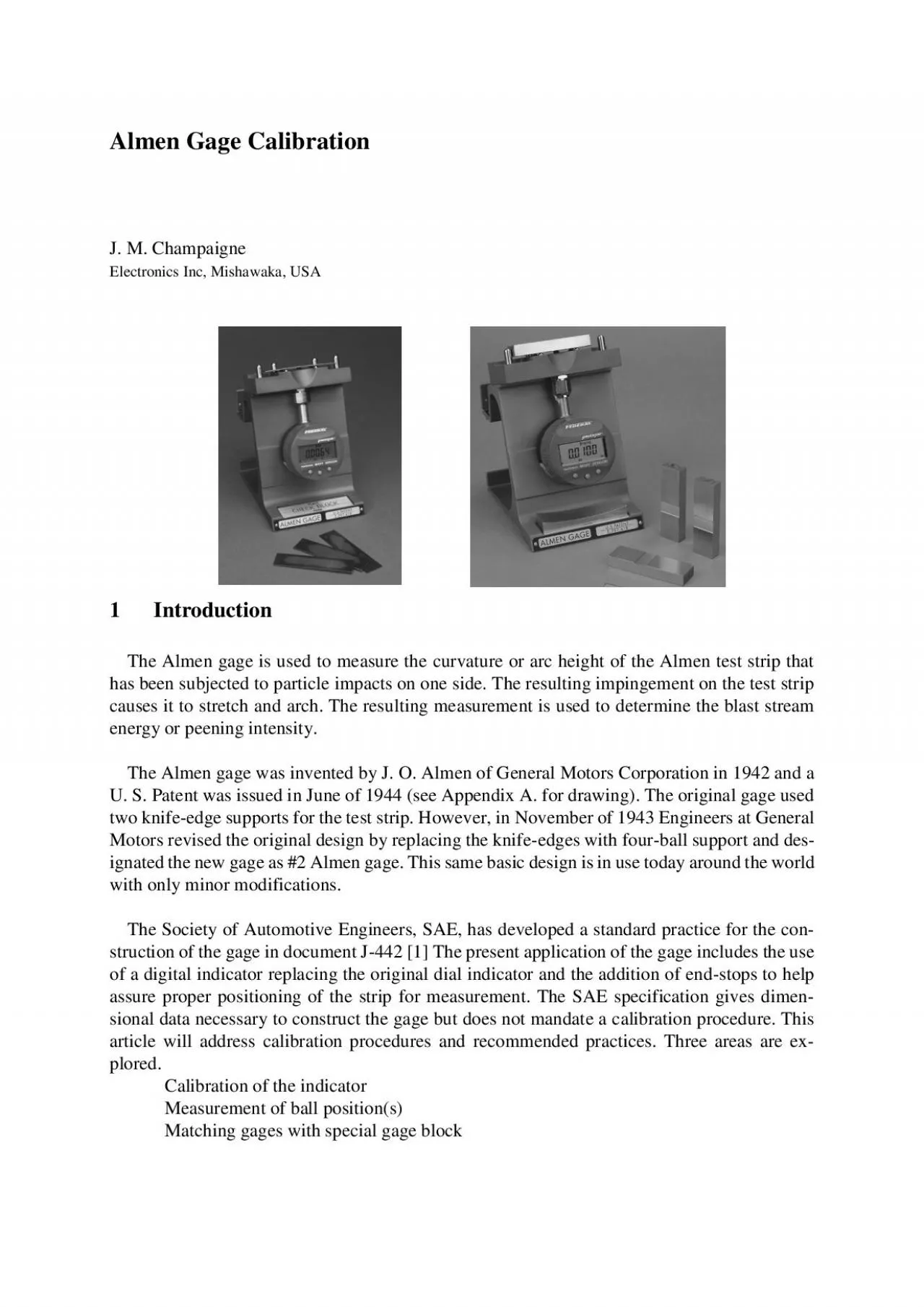
J M ChampaigneElectronics Inc Mishawaka USA1IntroductionThe Almen gage is used to measure the curvature or arc height of the Almen test strip that causes it to stretch and arch The resulting measureme ID: 873619

ball gage figure calibration gage ball calibration figure indicator block balls flatness almen position plane curved template test method

Share:

Link:

Embed:

Download Presentation from below link

Download Pdf The PPT/PDF document "Almen Gage Calibration" is the property of its rightful owner. Permission is granted to download and print the materials on this web site for personal, non-commercial use only, and to display it on your personal computer provided you do not modify the materials and that you retain all copyright notices contained in the materials. By downloading content from our website, you accept the terms of this agreement.


Presentation Transcript

1 Almen Gage Calibration J. M. Cham
Almen Gage Calibration J. M. Champaigne Electronics Inc, Mishawaka, USA 1 Introduction The Almen gage is used to measure the curvature or arc height of the Almen test strip that causes it to stretch and arch. The resulting measurement is used to d etermine the blast stream energy or peening intensity. The Almen gage was invented by J. O. Almen of General Motors Corporation in 1942 and a two knife - edge sup ports for the test strip. However, in November of 1943 Engineers at General Motors revised the original design by replacing the knife - edges with four - ball support and des- he world with only minor modifications. The Society of Automotive Engineers, SAE, has developed a standard practice for the con- struction of the gage in document J - 442 [1] The present application of the gage includes the use ng the original dial indicator and the addition of end - stops to help assure proper positioning of the strip for measurement. The SAE specification gives dimen- sional data neces

2 sary to construct the gage but does not
sary to construct the gage but does not mandate a calibration procedure. This art plored. Calibration of the indicator Measurement of ball position(s) Matching gages with special gage block 2 Calibrate the Indicator Primary importance is often assigned to the dial indicator accuracy and performance and it is often the only element of the gage that is calibrated. Most large aerospace firms and calibration laboratories are capable of calibrating the indicator. 2.1 Co mmercial Calibration Stand A commercial indicator calibration stand is shown in figure 1. This is a common tool used to calibrate analog or digital dial indicators and it offers a high degree of precision. Unfortunately it is expensive and time - consuming t o use this method of calibration. Figure 1. Commercial indicator calibration stand 2.2 Calibration Step Blocks A simpler method of indicator calibration using precision step - type gage blocks can be em- ployed. These blocks, shown in figure 2, have a flat d

3 atum reference surface and a slot of pre
atum reference surface and a slot of precise depth from that surface. Since the gage block is not as long as the Almen strip it is allowed to slide from side to side on the gage platform and thereby allow the indicator tip to rest upon either the d atum reference or the slot. This technique precludes having to dismount the indicator from the gage frame, another timesaving feature. Using a set of such blocks with convenient slot depths can provide a quick and easy indicator calibration. [3] Figure 2a. Step block used to calibrate digital indicator Figure 2b. Step block to left for zero Figure 2c. Step block to right for calibration (inch mode) 3 Ball Position Ball position is very important for proper operation of the gage. In addition to ball placement the condition of the balls, namely flatness, is another important factor in gage accuracy. 3.1 Ball Placement Incorrect ball placement can contribute to erron eous readings. There are two common meth- ods available to determine if ball p

4 lacement is within specified limits. One
lacement is within specified limits. One method is to use computer controlled measuring equipment such as a coordinate measuring machine, CMM. These ball position measurements can then be compared to the requirements of J - 442 to verify compliance. A special template, shown in Figure 3 can be used to validate proper positioning of the balls. This type of test is more accurately described as a “conformity” test since no numerical data is generated. It is a go - no - go affirmation of ball placement integrity. The template is placed on the gage and visual inspection should reveal that all four balls are visible within its respective tem- plate hole. If any ball is out of position it will be r eadily apparent upon inspection and the gage can be rejected for non - compliance. Another feature of this particular template is its thickness. It is 2mm thick, the specified minimum ball height requirement. Each of the four balls must extend above the top plane of the template to meet the 2mm ball height requirement an

5 d sliding a straight edge over the surf
d sliding a straight edge over the surface and detecting the “obstruction” presence of each ball easily affirm this. Figure 3. Special template to verify position of 4 - balls 3.2 Ball Flatness SAE guidelines now dictate that balls shall be replaced “….whenever any visible signs of flatness are observed.” The importance of this is illustrated in Figure 4 that shows a schematic of a gage with a curved test specimen tha t measures .024 inch deflection or arc height. With balls in a flat condition the resulting gage reading increases. The “ideal” reading of .024 inch has changed to almost .030 inch, approximately 25% increase in reading. [2] Figure 4a. Reference zero and ideal reading .024“ Figure 4b. Flat ball co ndition results in .030“ reading 3.3 Ball Plane Flatness Another tool is needed to affirm ball plane flatness, which is specified in SAE J - 442 to be .05mm. Although it is not difficult to use con ventional dial i

6 ndicators it has been found to be much
ndicators it has been found to be much easier to place a known flat surface, such as shown in Figure 5, onto the measuring posi- tion. Individual balls are adjusted for height until the template does not “rock” back and forth or tilt. The bal l plane flatness is easily obtainable with this technique. Any non - plane flatness greater than .005mm causes a very noticeable rocking or tilting which can be easily detected. 4 Matched Calibration Gages Manufacturing tolerances in such a complicated device can result in non - uniform readings from gage to gage even though the gage is technically “in compliance” with the construction requirements. It would be desirable to offer “matched calibrated gages”, especially when a gage might be taken out of service and its replacement might give different readings. Such an oppor- tunity exists when using the calibrated curved block. A special curved block was review ed by the National Institute for Standards and Technology (NIST) in Washington, DC

7 and a value with an estimate of uncerta
and a value with an estimate of uncertainty was assigned to the block. After placing the curved block into measuring position the gage can be re - calibrated to match the valu e of the curved block, thus assuring gage - to - gage reproducibility. [4] Figure 5 .Flat block used for checking for ball plane flatness 4 References [1] SAE J - 442 (Dec 2001 ) Test Strip, Holder and Gage for Shot Peening, The Society of Au- tomotive Engineers, Warrendale, PA, USA [2] Champaigne, J, Almen Gage Accuracy and Repeatability, 1993 Oxford, England Pro- ceedings of Fifth International Conference on Shot Peening 16 - 27 [3] Champaigne, J, U S Patent 5,780,714 1998 Calibration Apparat us and Method for Shot Blast Intensity Measurements [4] Champaigne, J. U S Patent 6,289,713 2001 Method of Calibrating Gages used for Measur- ing Intensity of Shot Blasting Appendix A Almen, J. O. U.S. Patent 2,350,440 1942 Figure 6. Curved block used to calibrate matched gage