/
Pellet Burnerinstallation or operating the heater.  Failure todamage, Pellet Burnerinstallation or operating the heater.  Failure todamage,

Pellet Burnerinstallation or operating the heater. Failure todamage, - PDF document

elina
elina . @elina
Follow
343 views
Uploaded On 2020-11-25

Pellet Burnerinstallation or operating the heater. Failure todamage, - PPT Presentation

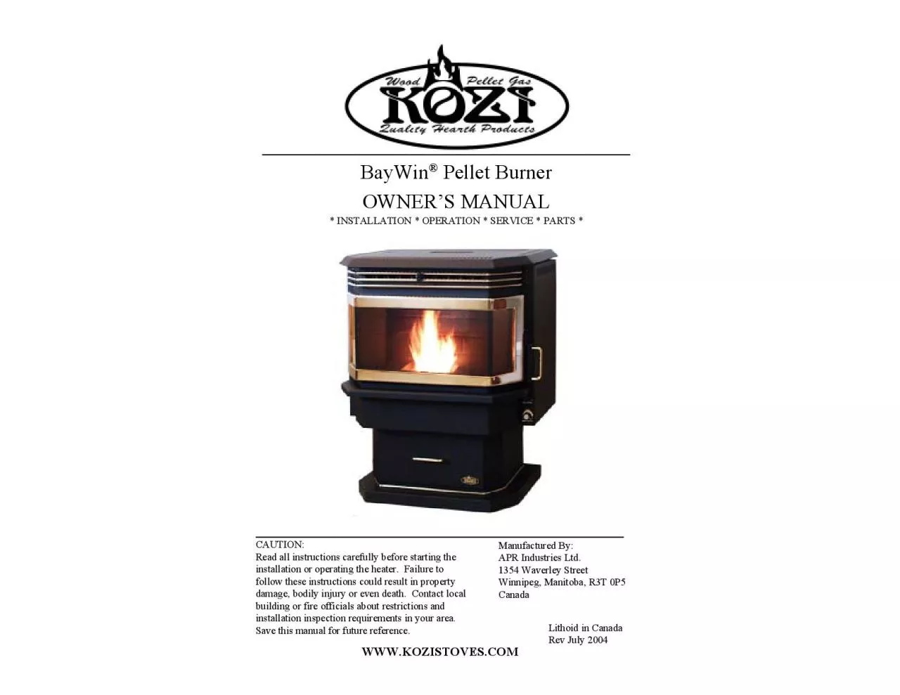
Manufactured By Lithoid in CanadaRev July 2004 WWWKOZISTOVESCOM Page 2 CAUTION Stove has moving parts Disconnect power Page 3 I Installation and Operation Manual ID: 825086

fan heater burn air heater fan air burn feed venting fuel exhaust insert mobile pot pellet inches page installation

Share:

Link:

Embed:

Download Presentation from below link

Download Pdf The PPT/PDF document "Pellet Burnerinstallation or operating t..." is the property of its rightful owner. Permission is granted to download and print the materials on this web site for personal, non-commercial use only, and to display it on your personal computer provided you do not modify the materials and that you retain all copyright notices contained in the materials. By downloading content from our website, you accept the terms of this agreement.


Presentation Transcript

Pellet Burnerinstallation or operating t
Pellet Burnerinstallation or operating the heater. Failure todamage, bodily injury or even death. Contact localManufactured By:Lithoid in CanadaRev July 2004WWW.KOZISTOVES.COMPage 2CAUTION: Stove has moving parts. Disconnect powerPage 3I. Installation and Operation Manual...................................................41. Preamble: Instructions for Safe Installation and Operation...................................................42. Clearance to Combustible Walls................................................................................................52.1 Non-Combustible Floor Protector....................................................................................52.2 Free Standing Stove..........................................................................................................62.3 Free Standing Installed in an Alcove................................................................................62.4 Insert Installed in an Alcove........................................................................

.....................2.5. Insert Instal
.....................2.5. Insert Installed in a Masonry/Factory Built Fireplace.....................................................62.6 Other Clearances and Recommendations.........................................................................63. Electrical Requirements.............................................................................................................74. Fuel Requirements......................................................................................................................85. Venting System............................................................................................................................85.1 Exhaust Vent Pipe Requirements.....................................................................................8Termination Requirements.........................................................................95.3 Combustion Air Intake Requirements............................................................................106. Location of the Heater..............................

........................................
................................................................................117. Typical Installation Configurations.........................................................................................11 BayWin ® Pellet Insert Additional Considerations..................................................13 BayWin® Pellet Insert Additional Requirements..............................................138.2 Surround Assembly........................................................................................................1 BayWin® Pellet Insert Installation....................................................................14 BayWin® Pellet Insert Removal.......................................................................158.5 Operation and Maintenance............................................................................................159. Mobile Home Additional Installation Requirements.............................................................159.1 Combustion Air Intake Requirements.........................................

...................................159.2
...................................159.2 Exhaust Vent Requirements...........................................................................................169.3 Other Installation Requirements.....................................................................................169.4 Typical Mobile Home Installation Configuration...........................................................16Home Installation...........................................................17II. Understanding Your Pellet Burning Heater.................................181. CDescription............................................................................................................181.1 General Overview...........................................................................................................181.2 Exhaust Fan....................................................................................................................181.3 Burn Pot.........................................................................................................

.................181.4 Circulation Fan.
.................181.4 Circulation Fan...............................................................................................................181.5 Trouble Shooting Module Status Lights.........................................................................191.6 Auger Cycle Timer.........................................................................................................1.7 High Temperature Manual Reset Thermal Disk.............................................................191.8 Pressure Switch...............................................................................................................192. Heater Operation......................................................................................................................192.1 Circulation Fan Speed Control.......................................................................................202.2 Start Button.....................................................................................................................202.3 Feed Control......

........................................
.............................................................................................................202.4 Damper Control..............................................................................................................202.5 Starting (lighting) your Heater for the First Time...........................................................202.6 Starting (lighting) your Heater........................................................................................212.7 Stopping your Heater......................................................................................................2.8 Adjusting your Heater.....................................................................................................III. Maintenance...................................................................................22IV. Trouble Shooting Guide................................................................25V. Diagrams and Parts List.................................................................27 BayWin® Circuit Diagram..........

........................................
...............................................................................272. Stove Cross Section...................................................................................................................283. Equipment ...294. Parts List....................................................................................................................................305. Accessories List.........................................................................................................................31VI. Warranty.........................................................................................31Page 4instructions carefully before starting installation. Save this manual for future reference.1. Preamble: Instructions for Safe Installation and Operationstanding you Pellet Burning Heater” section) If you are unsure, ask4. Oil the circulation fan motor bearings every 6 months. See the “Mainte-minimum of 6 inches (150mm) in front of the heater. This is to catch7. Use only UL/ULC listed Type Pl or Type L venting

for the exhaustin the venting system ar
for the exhaustin the venting system are unavoidable. For details see the “Venting8. Combustion of wood pellet fuel deposits ash in the heater and ventingfuels). Refer to the “Maintenance” section for more information.9. The heater must be turned OFF and allowed to cool completely beforePage 5silicone sealer (RTV). Aluminum tape is not an adequate sealant.tory in mobile home installations. Connect the air intake of the heatercode for Canada and the NFPA 70 code for the USA. Also, this heater14. Do NOT operate the heater with the door open. Make sure the door isclosed tightly during operation. Inspect the gaskets of the doorthe manufacturer. See WWW.KOZISTOVES.COM or contact your2. Clearance to Combustible Walls pellet stove with a non-A. Depth of Floor Protector32 inches (815 mm)B. Width of Floor Protector27 inches (680 mm)C. Floor Protector to Front of Unit6 inches (150 mm)D. Width of Unit25 inches (635 mm)E. Depth of Unit25 inches (635 mm)Page 6A. Side Wall to Unit12 inches (300 mm)B. Back Wall to Unit1 inch (25 mm)C.

Corner to Unit1 inch (25 mm)Minimum wi
Corner to Unit1 inch (25 mm)Minimum width48 inches (1220 mm)Minimum height48 inches (1220 mm)Maximum depth30 inches (760 mm)Minimum width48 inches (1220 mm)Minimum height38 inches (965 mm)Maximum depth30 inches (760 mm)D. Floor protector 6 inches (150 mm)E. Combustible side wall to unit12 inches (300 mm)F. Mantle to unit13 inches (330 mm)G. Top facing to unit13 inches (330 mm)H. Side facing to unit12 inches (300 mm)information. Please note the certification label supersedes any information contained in2.6 Other Clearances and Recommendations1. This heater must be mounted on a non-combustible material, placedunderneath the heater and extending a minimum of 6 inches (150 mm)2. A safety certification label has been attached to either the back of theheater or inside the hopper lid. A diagram of a sample label is3. Clearances can ONLY be reduced by means approved by local buildingPage 7Figure 2 Certification LabelINSTALLATION COMMENT: We recommend sufficient space beprovided (minimum 20 inches/500 mm) on each side of the heater toser

vice the equipment area. If this is not
vice the equipment area. If this is not possible, a provision must bemade to pull the heater out for service.3. Electrical Requirements 1. This heater is an electrical appliance. The North American versions of thisappliance require 120 Volts, 60 cycle and 3 Amps of electrical power. TheEuropean versions of this appliance require 230 Volts, 50 cycles and 2 Amps 3. When installed in mobile home, the heater must be grounded to the4. Fuel Requirementstoo much fines and saw dust must be screened before use. DO NOT use wet pellets. It ishigh ash content fuels. These “poor” fuels cause the burn pot to clog much morefrequently and do not provide the proper air flow for a clean, effective burn. “Poor”Section 5: Venting SystemSection 6: Location of the HeaterSection 7: Typical Installation Configurations pellet heaters have a negative pressure combustion chamber. A high pressure,(vacuum) inside the burn chamber. Air from outside the heater then rushes through thethe burn pot it is used to burn the pellets. A proper size ULC/UL listed type

PL or L KOZI pellet burner is certified
PL or L KOZI pellet burner is certified for 3 and 4 inch exhaust venting. 3 inch venting issufficient for most direct vent installations. However, installations with several elbows,which reduces the volume of air movement and creates burn problems. The use of 4 inch 2. The heater comes with a 5 ft (1.5 M) long, grounded, electrical cord suitablepositive pressure. At least 3 screws are needed for securing all joints for connector pipes.leakage of exhaust fumes into the house. If you smell smoke, the venting has not beenproperly sealed. Use only high temperature RTV silicone for sealing. Aluminum tape isThe venting of this heater is not allowed to pass through any closets, concealed spaces,through a floor, ceiling or attic space. If the venting is to go through a wall or combus-Burning Appliance and Equipment CAN / CSA -B365. For more detailed venting5.2 Exhaust Vent Termination Requirements1. The exhaust vent must terminate into an open space. Under noclosed spaces. Venting into a garage, under a sun deck, porch or anyfor each

90° Elbow or T fitting= add 5 EVLfor eac
90° Elbow or T fitting= add 5 EVLfor each 45° Elbow= add 3 EVLfor each Horizontal run of vent= add 1 EVL per foot of horizontal ventingfor each Vertical run of vent= add 1/2 EVL per foot of vertical ventingTHE INSTALLATION. IT IS A FIRE HAZARD.DO NOT INSTALL A FLUE DAMPER IN THE EXHAUSTVENTING SYSTEM OF THIS HEATERDO NOT CONNECT THIS HEATER TO A CHIMNEYFLUE SERVING ANOTHER APPLIANCEThe EVL is 15 or moreCAUTION: EVL CANNOT EXCEED 25ft (7.6 meters). Installations2. The exhaust vent must be at least:3. The exhaust vent opening must be a minimum of:4. The exhaust air is EXTREMELY HOT. Caution must be taken to avoid5. The vent terminal must have an end cap to protect against down-draft5.3 Combustion Air Intake RequirementsThere are 2 methods of supplying the heater with combustion air. They are as follows:1. Room Air: Conventional homes may use room air for combustionprovided APR Part No: CV100 (Check Valve) is installed. Forinstallations where the exhaust pipe incorporates a minimum 3’ verticalValve) is optional. In this venting co

nfiguration it is highly recom-2. Outsi
nfiguration it is highly recom-2. Outside Air: All installations can be connected to the exterior of thelength of intake exceeds 3’ (1 meter) or has several bends. Use ofmance. If your heater burns poorly, experiences roll-out or back-drafts, outside combus-1. Use of plastic pipes is not permitted under any circumstance.INSTALL ALL VENTING AT CLEARANCESSPECIFIED BY THE VENT MANUFACTURERPage 117. Typical Installation Configurations2. The combustion air intake must terminate into a vented space, i.e.3. The elevation of the combustion air intake must be below the exhaust4. Excessive lengths and elbows on the air intake pipe will cause airflowrestrictions. A minimum of 2 inch (50 mm) or larger venting should beused for lengths exceeding 3’ (1 meter). Increase the venting size asA. This heater is NOT approved for bedroom installations.B. If installed in a mobile home, the heater must be anchored to the floor.C. When installed in a conventional or mobile home, check for:a. Clearance to combustibles.d. Power within 5 feet (1.5 m).b. S

ufficient room to service the unit.e. Ac
ufficient room to service the unit.e. Access for exhaust venting.c. Access for outside combustion air.f. EVL not exceeding 25 ft (7.6 m).Figure 3. Typical floor plan - corner installationFigure 5. Free standing through the roofFigure 7. Free standing basementFigure 8. Free standing through aFigure 6. Free standing through theFigure 4. Free standing through the wall installationFigure 9A. Factory built zero clearance or8. KOZIKOZIKOZIKOZIKOZI BayWin ® BayWinfireplace. The insert’s overall dimensions are 25” (635 mm) in width, 25” (635 mm) indepth and 23” (585 mm) in height. The minimum opening of a fireplace that is suitable pellet insert is 22” (560 mm) wide, 19.5” (500 mm) high and 16” (410 mm)deep. The minimum clearances for an insert installed in a masonry or listed factory builtFigure 10. Minimum Fireplace opening for the pellet insert.8.1 KOZI BayWin pellet insert in a masonry or listed factory built1. The room air must be sealed from the exterior. This can be achieved by9A) or at the chimney damper (see figur

e 9B).2. When installing the insert and
e 9B).2. When installing the insert and its surround, the air flow of the existingfireplace must not be altered. Make sure no louvers, cooling air orFigure 9B. Factory built zero clearance orPage 148.3 KOZI BayWin 1. Verify that the fireplace opening meets the insert’s minimum require-2. Attach and seal the exhaust venting to the terminal using sheet metal3. Insert the venting into the existing chimney and secure the terminal tothe chimney. Ensure that the venting and chimney are properly sealed.4. If outside combustion air is being used, install the air intake as3. When installing an insert, a full height listed chimney liner must becavity as shown in figure 9B. The junction of the chimney liner to theseal plate must be properly sealed. This chimney liner must be4. A permanent metal tag must be attached to the back of the fireplace.A. For installation of a chimney liner, the chimney damper may be removed. not affect the operation of the fireplace upon removal and they can be reassembled when the insert is rem

oved.8.2 Surround Assembly pellet inse
oved.8.2 Surround Assembly pellet insert surround can be seen inFigure 11. The surround comes in 3 separateattached to the heater. Layout the top and sides ofaligned with the top piece mounting holes. Usingthe top. Your surround is now ready to mount tothe insert. pellet insert surround6. Place the insert part way into the opening.8. If the top of the chimney was not sealed to the vent terminal in step 3,9. Plug the power cord into the electrical outlet.10. Assemble the surround (if not previously assembled) and slide it on11. Push the insert into the cavity until the surround touches the existing8.4 KOZI the fireplace. For example, venting may need to be resealed, parts may need to beinstallation with the following exceptions: make sure the insert is not operating, has hadsufficient time to cool down and that power to the insert has been removed. Now you8.5 Operation and Maintenancehopper. On a pellet insert, the hopper opening is much smaller than the stoveversion. To load fuel into the insert, remove the cover plate fr

om the top of the insert,pour fuel into
om the top of the insert,pour fuel into the opening and replace the cover plate. DO NOT place hands inside theopening to the hopper. There are moving parts in the hopper which can cause bodilystove. Please read the “Maintenance” section for instructions on cleaning your insert,9. Mobile Home Additional Installation Requirements9.1 Combustion Air Intake Requirementsair taken from the outside. The APR Part No: CV100 (Check Valve) CAN NOT be usedto provide internal combustion air from the mobile home to the heater. This heater mustwith a minimum 2 inch (50 mm) diameter. Use of plastic pipes are not permitted. PleasePage 16home. Please refer to the “Typical Mobile Home Installation Configuration” section fortypical venting configurations. It is highly recommended that a minimum verticalventing of 3 ft be used (as shown in Figure 13). This will reduce the chance of smoke1. The heater must be securely anchored to the floor of the mobile home.There are 2 holes located on the base of the stove near the back. Usethe floor of the mobil

e home.Figure 12. Anchoring Holes for M
e home.Figure 12. Anchoring Holes for Mobile Home Installations2. There must be a non-combustible floor protector placed underneath the3. This heater can not be installed in any sleeping room of the mobile4. The heater must be grounded to the steel chassis of the mobile home(unless this is not required by local code).The following figures describe some typical installations for mobile homes. Variations ofthese are possible. Common sense, safety and compliance with local building codes mustWARNING: DO NOT INSTALL IN A BEDROOM OF A MOBILE HOMECAUTION: THE STRUCTURAL INTEGRITY OF THE FLOOR, WALLFigure 14. Mobile home installationFigure 15. Mobile home installa-9.5 Recommendations for Mobile Home Installation1. Make sure there is an effective vapor barrier where the ventingpenetrates to the outside of the mobile home. Seal all openings in the2. Make sure the mobile home has adequate ventilation. Your stove is asolid fuel burning appliance. As such, there is a possibility of smokeentering the room. By making sure the mobile home

is adequately3. Make sure the venting
is adequately3. Make sure the venting is properly installed and sealed. Leaking ventingmay set off smoke detectors in the mobile home. Also, some fuels mayproduce carbon monoxide which, in large amounts, can be fatal. MakeFigure 13. Mobile home installation4. If parts become damaged or need to be replaced, please contact yourlocal dealer or visit WWW.KOZISTOVES.COM. Do NOT replace1. Component Description heater is to familiarize yourself with itsoperation. Your heater has 3 main systems: Combustion, Circulation and Feed. Thecombustion system includes the air intake, burn pot, exhaust fan and exhaust venting.The circulation system consists of a circulation fan, fan speed control and heat ex-changer. The feed system is made up of an auger motor and various safety devices.Each part of these systems will be described later in detail. A description of theexchanger and pushes it through the venting. This fan is a fixed speed fan which turnsON whenever the heater starts and remains ON until the heater is cool. THIS FANCANNOT BE TURN

ED OFF MANUALLY. Failure of this fan wi
ED OFF MANUALLY. Failure of this fan will result in a feedThe burn pot is the receptacle in which the pellet fuel is burned. This portion of theprocess. It is recommended the burn pot be cleaned every time the hopper is filled andexchanger and back into the room as hot air. The circulation fan speed can be controlledby the fan speed control (described later). The control system has a built-in safety thatallows it to override the fan speed control in the event the heater overheats. As yourexcess heat. As your heater cools, the circulation fan will return to it’s original setting.Page 19In conjunction with the feed control, the auger cycle timer controls the feed rate. This isachieved by turning the auger motor ON and OFF. Failure of this component will resultin a status light change. Refer to the “Trouble Shooting” section for more details.The manual reset thermal disk is a high temperature safety switch. If the heater shouldreach an unusually high temperature, this switch will shut the feed system OFF. Thetemperature. Once this

switch has been tripped, the control sy
switch has been tripped, the control system will not allow anymore fuel to feed into the burn pot until it has been manually reset. DO NOT RESETTHIS UNIT UNTIL THE CAUSE HAS BEEN FOUND AND REPAIRED. Failure ofthis component will result in a status light change. Refer to the “Trouble Shooting”is under vacuum. Failure of the exhaust fan or leakage in the heater (such as opening thedown of the feed system. Refer to the “Trouble Shooting” section for more details.Speed, Feed Rate, Damper and Start button. These 4 controls will allow you to adjustand operate your heater safely and efficiently. The location and method of adjustmentFigure 16. Trouble shootingYour heater is equipped with 3 status lights. Eachwhat is happening in the feed system. The top lightpressure switch. In normal operation, all 3 lights willcontrol setting (see “Heater Operation”). Should anyDIM. If this occurs, please refer to the “TroublePage 20Turning this knob counter-clockwise turns the circulation fan OFF. Rotating the knobclockwise decreases the speed of

the circulation fan from High to Low. I
the circulation fan from High to Low. It is NOTand puts the circulation fan on high speed.2.4 Damper ControlThe damper control rod is located on the left side of the heater. This rod controls theamount of air passing through the burn pot. By pushing the control rod in, you reducethe amount of air passing through the burn pot. By pulling the rod out, you will increase1. Fill the hopper with pellet fuel. At this time the auger tube is empty. It2. Turn the feed control knob clockwise to high.3. Press the start button. The exhaust and circulation fan should come ON4. Monitor the burn pot (located inside the burn chamber, see “StoveCross Section” diagram for exact location). Once pellet fuel begins tomately 12 o’clock setting.). If the heater turns OFF before fuel beginsto drop into the burn pot, repeat steps 3 and 4.Figure 17. Control panelbutton is the first step in starting the heater. Thefor 15 minutes. The heater will switch to theOFF. To allow the heater to run for another 15Turning the knob in the counter-clockwise dire

ction will turn the feed OFF. As the kn
ction will turn the feed OFF. As the knob5. Once fuel has accumulated in the burn pot, the igniter will lite the fuel1. Ensure there is adequate fuel in the hopper and that all ashgates anddoors are closed. Open ashgates/door will turn OFF the feed system.2. Turn the fuel feed knob to desired setting. (If in doubt, adjust to 123. Adjust damper to approximate setting. (If in doubt, pull open to4. If your heater is equipped with an “electric start”, proceed to step 9. In5. Open the burn chamber door and place a handful of fuel in the burnpot. The burn pot should be approximately 1/4 full with wood pellets.6. Pour lighter gel on pellets in the burn pot.7. Ignite lighter gel with a barbecue lighter and allow the pellets to catchfire. DO NOT ATTEMPT TO IGNITE HOPPER FUEL ON FIRE.8 Close the combustion chamber door.9. Press the start button. The following should happen :a. The exhaust fan will start.b. The circulation fan will start at the fan speed control setting.c. The feed system begins to feed. The auger and troub

le shooting lights should begin to bl
le shooting lights should begin to blink. minutes.12. If the heater shuts OFF during the start up cycle and there is still aDO NOT BURN GARBAGE OR FLAMMABLE FLUIDS SUCH ASGASOLINE, NAPHTHA OR ENGINE OIL.HOT WHILE IN OPERATION. KEEP CHILDREN, CLOTHING ANDFURNITURE AWAY. CONTACT MAY CAUSE SKIN BURNS.WARNING: Make sure the amount of fuel in the burn pot does notexceed the height of the burn pot at any point during operation. ThisPage 222.7 Stopping your Heaterposition. This will cause the feed system to stop (trouble shooting lights will stopblinking) and the flame should die out within 5 minutes. The exhaust fan and circulationfan will continue to run until you heater is cold (approximately 30 minutes). DO NOTclosed OR if the wrong size of venting is used. It is equally important that you use goodquality, wood pellet fuel. A poor quality fuel will create poor and unsatisfactoryTo increase the heat output of your heater, slightly increase the feed rate by turning theslightly or increase the amount of combustion air. In few m

inutes the size of the flamewill reduce.
inutes the size of the flamewill reduce. If the size of the flame is fluctuating between feed drops, this indicates theamount of combustion air is too much for the amount of feed. In this case, close the airdamper slightly and once again, allow the flame to stabilize. When reducing heat output,damper is open too far, there is a chance of extinguishing the fire. Some fuels have asetting is much lower, your heater is overheating. Reduce the feed rate as described - During normal operation, your heaterproduces a lot of flyash. This flyash will collect in the exhaust venting system andrestrict the flow of the flue gases. Incomplete combustion, such as occurs during startup,which also collects in the exhaust venting system. The soot and flyash which deposits inyour heater and venting system is harmful to the performance of your heater. Impropermaintenance leads to poor performance, component failure and can be dangerous. Please 1. Clean the venting system. If there is a significant amount of soot buildup, it should be removed to preven

t the risk of a chimney fire. Bylikelih
t the risk of a chimney fire. Bylikelihood of a chimney fire occuring. Please contact your local 2. Clean behind the back heat shield and exhaust passage. Ashes caneach corner of the heat shield. Using a brush, remove all of the ashesbelow the auger chute). Inspect the auger chute gasket at this time. 3. Clean the exhaust fan and housing. Ash accumulation on the fanblades will reduce the life of your exhaust fan. Frequent cleaning willhelp extend the life of this component. Refering to figure 18, open theleft side pannel to access the exhaust fan. Using a Common (flat head)the housing. Using a brush, clean all ash from the exhaust fan blades 4. Inspect the condition of the door gasket periodically and replace it asnecessary. It is important to make sure the door gaskets are in goodcondition. Gaskets in poor condition will not allow the door to seal 6. Perform weekly maintenance.Figure 18. Holes for screws onFigure 19. Oil ports on a 5. Oil the circulation fan motor. To oil the motor bearings, the right handside panel must

first be opened. This is done by removi
first be opened. This is done by removing the 2 screwsnear the front of the stove as shown in Figure 18. Use a Robertsonscrews. You will now be able to swing the panel open and access thecirculation fan. There are 2 oil ports located on the top of the motor,There may be rubber plugs in one or both of these oil ports. Theseplugs must be removed prior to and replaced after oiling. Place a few 1. Pull and push the cleaning rod which is located in the center, above thesignificant amount of ash on it. Dump the ashes into the burn 3. Using a brush, clean the top heat shield and remove it from the heater. 4. Remove the burn pot and burn pot stand and clean them thoroughly. 5. Using the brush, clean the walls and floor of the burn chamber. 6. Open the ashtray slightly and pull on each ash gate until the ash fallsfrom the burn chamber into the ashtray. Sweep remaining ashes intothe ashtray. For insert models, scoop out the ashes into a metal 7. Close the ash gates and remove the ashtray. Dispose of the ashes in asecure. DO NOT place the

container on a combustible surface. - A
container on a combustible surface. - Ashes should be placed in a metal container with a tight fitting lid.ground, well away from all combustible materials, pending final disposal. If the ashesthe closed container until all cinders have been thoroughly cooled. Do not place any 8. Re-install all removed parts in their original positions. 9. Clean the glass with a mild glass cleaner when dirty. DO NOT cleanthe glass when the door is hot. Cleaning the glass will allow you to seethe flame and how it is burning. This is very important to see if theheater is burning properly or not. DO NOT hit the glass or slam thedoor shut. This may cause the glass to crack or break. DO NOTfactory approved glass. If the glass cracks or breaks, turn the heaterOFF. DO NOT operate the heater until the glass has been replaced.After each heating season: 1. Remove all the pellet fuel form the hopper. Run the heater to emptythe auger tube. Vacuum the hopper and auger tube. Clean the rest ofIV. Trouble Shooting Guide BayWin is equipped with trouble shoot

ing module status lights located at theb
ing module status lights located at theback bottom right hand corner of the heater. This module consists of a set of three redlights. Under normal working conditions, while the heater is operating, all three lightsare BLINKING (ON and OFF). The rate of blinking is proportionate to the fuel feedrate. The higher the feed rate, the faster the lights will blink. Any time the sensors detectPage 26Note: For safety, contact a qualified serviceman for all repair work.PROBLEMLIGHT STATUSPOSSIBLE CAUSESam.er motor failed.2. Replace auer motor.er slippin.3. Tihten au1. Pressure switch failure.1. Replace ressure switch.or loose.2. Replace pressure switch tube.4. Exhaust fan failure.4. Replace exhaust fan.ect Door, Ash6. Burn pot plugged.6. Clean Burn Pot.2. Auger cycle timer failed.2. Replace auger cycle timer.3. Start button defective.3. Replace push button start.p1. Stove in “Cool Down”.1. Allow sufficient cool down time.2. Defective auto thermal disk.2.Replace auto thermal disk.3. Control 15 minute timer.3. Repl

ace timer.ellet fuel.1. Add ellet fue
ace timer.ellet fuel.1. Add ellet fuel to hopp2. Igniter failure.2. Replace igniter fuse and igniter.ot dirt.3. Clean burn pN/A1. Burn pot dirty.h air.1. Ad2. Too much fuel.2. Reduce feed rate. 1. Too much air.1. Reduce air damper.2. Clean heat exchanger. See ualit fuel.3. Change fuel supp1. Not enough air.1. Adjust air damper, Clean stove.2. Too much fuel.2. Adj1. Too much air.1. Reduce air damp2. Feed rate set too low. 2. Increase feed rate.1. Too much air.1. Reduce air damp2. Feed rate set too low. 2. Increase feed rate.Smell of smoke in room.N/A.1. Reduce the feed rate.2. Fan Thermal Disk Failed.2. Replace Fan Thermal Disk.3. Fan Speed Control Failed.3. Replace Fan Speed Control.pN/A1. Normal Operation.1. Close door.Stove won’t turn OFF.N/AShort flame on high feed.N/ANot enough Heat output.N/APage 27V. Diagrams and Parts List1. KOZIKOZIKOZIKOZIKOZI BayWin® Circuit DiagramPage 282. Stove Cross SectionPage 293. Equipment CompartmentPage 304. Parts ListItem NoDescriptionPart No

1Pedestal Base Assembly (Black)BV12Gold
1Pedestal Base Assembly (Black)BV12Gold grillBV113Top Lid (Black)BV124Hopper Lid (Black)100235Back Cover Plate (Black)BV176Top Heat shieldBV197Back Heat Shield, Embossed Brick Pattern (Black)BV20, BV21Not ShownRight Side Panel (Black)BV14Not ShownLeft Side Panel (Black)BV158Auger Chute Gasket Kit10006-129Circulation Fan Gasket10036-110Exhaust Housing Mounting GasketNot ShownExhaust Fan Mounting Gasket10002-1XLNot ShownExhaust Fan Motor Mounting Gasket10031-1Not ShownDoor Rope GasketBV6-2Not ShownGlass Gasket Kit (Includes inner and outer glass gasket)BV911Auger Motor1003512Feed Control Switch1004413Push Button Start1004314Circulation Fan Speed Control1003815Circulation Fan Override, Thermal disk1003716Manual Reset, Overheat Thermal disk1003917Exhaust Fan 1003118Exhaust Temperature Thermal disk 10034XL19Static Pressure Switch1003220Static Pressure Switch Tube10033XL21Auto/Manual Timer1004122Electrical Cord1004223Auger Cycle Timer1004024Trouble Shooting Module Light1004625Circulation Fan1003626Wiring Harness10045XL27Exhaust Housing Box10002XL28Dam

per Kit (Includes Damper, Coil Handle, S
per Kit (Includes Damper, Coil Handle, Slide Bracket, Rubber Slider)10004XL29Exhaust Tube AssemblyBV2732Cleaning Rod (Includes Coil Handle)BV2233Complete Gold Door AssemblyBV6Not ShownDoor Handle/Positioner Kit (includes handle, pin, rollers…)BV4-4,BV4-534Center GlassBV735Side Glass (one only)BV836Glass holder kitBV4-337Burner Pot 10016XL38Burner Pot Stand10014XLAuger Rebuild Kit (Includes bushings, auger, auger holder, auger holder gasket, nut and bolt…)10006-7, 10008, 10008-4, 10035-140Complete Hopper/Auger Assembly10006Panels & TrimsGaskets & Gasket KitsElectrical ComponentsKits, Assemblies & Other ComponentsPage 315. Accessories List3. Ceramic Bricks5. Paint and Powder CoatingContact Your Dealer for Warranty Information.void if the heater is misused. It is the option of APR Industries Ltd. whether to repair orItem No.DescriptionPart No.41Igniter Replacement KitN/ANot ShownAir Intake KitAK100Not ShownAir Intake Check ValveCV100Not ShownHopper ExtensionHE2Not ShownInsert Loading ChuteLC100Optional EquipmentWWW.KOZISTOVES.COMPage 32W