/
Hall Thruster for Space Applications: Advanced Concepts and Hall Thruster for Space Applications: Advanced Concepts and

Hall Thruster for Space Applications: Advanced Concepts and - PowerPoint Presentation

ellena-manuel
ellena-manuel . @ellena-manuel
Follow
442 views
Uploaded On 2016-07-28

Hall Thruster for Space Applications: Advanced Concepts and - PPT Presentation

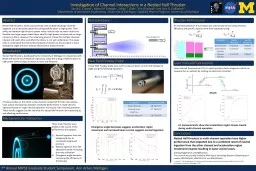
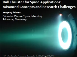
Yevgeny Raitses Princeton Plasma Physics Laboratory Princeton New Jersey 16 th International Conference on Ion Sources New York City NY August 28 2015 Outline Hall thruster Status quo ID: 422719

hall thruster field plasma thruster hall plasma field spoke wall electron current phys electrons 100 magnetic power transport effects

Share:

Link:

Embed:

Download Presentation from below link

Download Presentation The PPT/PDF document "Hall Thruster for Space Applications: Ad..." is the property of its rightful owner. Permission is granted to download and print the materials on this web site for personal, non-commercial use only, and to display it on your personal computer provided you do not modify the materials and that you retain all copyright notices contained in the materials. By downloading content from our website, you accept the terms of this agreement.


Presentation Transcript

Slide1

Hall Thruster for Space Applications: Advanced Concepts and Research Challenges

Yevgeny RaitsesPrinceton Plasma Physics LaboratoryPrinceton, New Jersey

16

th

International Conference on Ion Sources, New York City, NY, August 28, 2015Slide2

Outline

Hall thruster

Status quo

Frontiers applications

Two big issues unresolved for 50 years:

Wall erosion

Anomalous electron cross-field transport

Potential

solutions

New challenges: facility effectsSlide3

Hall

thruster

(HT)

e

e

E =-

v

e

 B

e

<< L <<

i

Diameter

~ 1-100 cmB ~ 100-200 GaussWorking gases: Xe, KrPressure ~ 0.1 mtorr Vd < 1 kV Power ~ 0.1- 50 kW

Thrust ~ 10-3 - 1N Isp ~ 1000-3000 secEfficiency ~ 6-70%

Unlike ion thruster, HT is not space-charge

limited.

Thrust density

is higher than in ion thrusters.

Limited by the magnetic field pressure, B

2

/2

.Slide4

Hall thruster spaceflight heritage

Status quo

: highly efficient 0.5-5 kW Hall thrusters used for station keeping, drag compensation, orbit transfer, moon mission.

Future:

rendezvous with asteroids and comets, interplanetary missions.

2010

First flight of US Hall thruster , 4kW, on operation GEO satellite mission.Slide5

Frontiers applications for Hall thrusters

Future space applications will take Hall thruster technology beyond and above its current status.

- low power < 500 W small and micro satellites.

- very low power < 10 W nano satellites.

- very high power 100 ‘s kW to support human exploration missions.

A NASA concept of a

300 kW SEP vehicle for human NEO missions.

The wingspan of the solar arrays

is 66 m.

A 100

kW

class nested-channel Hall thruster.(NASA-AFRL-Univ. Michigan)NASA Near-Earth-Object rendezvous

microspacecraft: 7 kg, 0.2m x 0.3m x 0.3m.A 50 W cylindrical Hall thruster. (PPPL)Slide6

1.35-kW SPT-100 New

1.35-kW SPT-100 5,700 Hrs

Ceramic channel, 10 cm OD diameter

Operational

Cathode

7 mm

Non-operational

cathode

Courtesy:

L. King

F. Taccagona

Issue # 1 (for all power levels): ion-induced channel and cathode erosion limiting thruster lifetimeSlide7

Issue # 2: anomalously high electron cross-field current limiting thruster efficiency

Thruster efficiency

Efficiency

reduces with increasing electron current across the magnetic

field.

Classical collisional mechanism can not explain the discharge current measured for Hall thrusters.

Enhanced cross-field current is usually attributed to anomalous fluctuation-induced (Bohm-type) diffusion

and

near-wall conductivity.Slide8

Hall thruster plasma research challenges

Development of predictive modeling capabilities for designing of the next generation Hall thrusters requires understanding:

Mechanisms of anomalous electron cross-field transport.

Plasma-wall interactions in the thruster and their effects: sputtering, electron emission, sheath instabilities, wall-induced electron transport.

Facility effects for high power thrusters vs. space environments.

Scaling laws for power/size/performance/lifetime.

Modeling needs to be multidimensional, multiscale fully kinetic (for electrons, ions, neutrals), and… validated.Slide9

Hall thruster plasma

Neutral density ~ 10

12

-10

13

cm

3

Plasma

density ~ 10

11-1012 cm-3

Highly ionized flow: ion/n > 100%Electron temperature ~ 20-60 eV

Ion temperature ~ 1 eVIon kinetic energy ~ 102-103 eV

Collisionless, partially ionized, non-equilibrium plasma with magnetized electrons and non-magnetized ions in non-uniform E ×B fields, and pressure gradients.

Median

Anode

WallExitMagnetic PoleSlide10

Electron-induced secondary electron emission (SEE) plays a very important role in Hall thruster operation

For ceramic materials, SEE yield is higher and approaches 100%

at

lower energies than for graphite and metals

.

Use of conductive channel walls can lead to short-circuit current (across magnetic field) increasing power losses.Slide11

SEE can strongly enhance electron flux from plasma to the wall

scs

 T

e

w

(x)

e

i

see

SEE

turns sheath to space-charge limited

regime (SCL).

In SCL, wall acts as effective heat sink for plasma increasing power losses.

When

When

Fluid Approach

Hobbs and Wesson, Plasma Phys. (1967)Slide12

Wall material effect on discharge characteristics

Segments of different SEE materials drastically can change

V-I characteristics

High SEE material

- Very low

SEE

material

Phys

. Plasmas (2006)Slide13

High-SEE

Very low-SEE

Wall material effect on electric field in plasma

IEEE Trans. Plasma Sci. (2010)

With very low SEE channel walls, the electric field is not far a fundamental limit for quasi neutral plasma ~

T

e

/



D

.Slide14

Simulations predict strong kinetic effects for

collisionless Hall thruster plasma

Hall thruster plasma, 2D-EVDF

Isotropic Maxwellian plasma, 2D-EVDF

Sydorenko et al, Kaganovich et al., Phys. Plasmas (2005, 2006, 2007 2009), Ahedo, Phys. Plasmas (2005)

Anisotropic

EVDF with beams of SEE electrons

travelling between walls.Slide15

SEE-induced electron cross-field transport

gives

SEE-induced cross-field current

The displacement

,

,

during the flight time

H/

u

bx

E

B

Exchange

of primary magnetized electrons by non-magnetized SEE

electrons induces so called near-wall conductivity across magnetic field.

Kaganovich, Raitses, Sydorenko. Smolyakov, Phys. Plasmas (2007)Slide16

Surface-architectured materials to mitigate SEE effects on thruster plasma

BN

Quartz

Macor

Dendritic

Re/W, Re/Mo

Graphite

Carbon Velvet

Carbon velvet

Surface-architectured materials

reduce

the effective SEE yield by trapping SEE electrons between surface

features.Slide17

Magnetically-shielded Hall thruster to mitigate adverse plasma-wall interaction effects

Unshielded

Low electron temperature near the wall

low sheath potential

1

Low energy of ions impinging the walls

low wall erosion  longer thruster lifetime.1Oblique magnetic field may prevent SEE electrons from flowing to the plasma   no near-wall conductivity.

I. Mikellides et al, Appl. Phys. Lett. (2013)R. Hofer, Michigan (2013)NASA JPL Hall Thruster with magnetic shield.ShieldedSlide18

Cylindrical Hall thruster (CHT)

Diverging

magnetic field

topology.

Operation

involves closed E

B

drift.

Electrons are confined in the hybrid magneto-electrostatic

trap. Ions are accelerated in a large volume-to-surface area channel. (potentially lower erosion).

Phys. Plasmas 8, (2001)

Cathode

100 W 2.6 cm CHTSlide19

Unusual focusing of the plasma flow in diverging magnetic field due to rotating electrons

Fisch

et al., Plasma Phys. Control. Fusion (2011)

Spektor et al., Phys. Plasmas (2010)Raitses at al., Appl. Phys. Lett.

(2007)

Pressure gradient

Centrifugal force

on E×B rotating electrons

Ion current in plume

LIF measurementsSlide20

Plasma non-uniformities (spoke) in Hall thruster

Spoke frequency

~ 10 kHz

10’s times slower than E/B

Spoke frequency >>

ci

12 cm diameter, 2kW Hall thruster

Unfiltered high speed imaging

Xenon operationSlide21

From probes and camera, strongest m=1 mode

spoke near the anode where B~0.5 kGauss

Direction

:

ExB

Velocity

:

1.2-2.8 km/s

E/B:

30 km/s

Via 1-3 km/sSize: 1.0-1.5 cmLocal wavenumber-frequency spectrum

J. Parker, Y.

Raitses, N. J. Fisch, Appl. Phys. Lett., (2010)Langmuir probes to measure spoke in CHTHigh speed imagesSlide22

More than 50% of the discharge current is conducted to the anode through the spoke

Segmented anode

The evaluation of the segment current

Ellison,

Raitses

,

Fisch

, Phys. Plasmas 19 (2012)Slide23

Phenomenology of

-

current through the spoke

B

r

E

0z

+

-

+

+

-

-

-

-

-

+

+

+

E

0z

×

B

E

θ

E

θ

×

B

Initial

density

perturbation,

Only electrons undergo azimuthal drift

motion,

E

θ

generated across the

perturbation,

E

θ

×B

drift across the magnetic field,

to

the

anode.

Correlated density and

E

fluctuations

would explain enhanced electron

transport.

Possible instability mechanisms: modified Simon-Hoh, Kelvin-Helmholtz, ionization instabilities.Slide24

Can spoke be suppressed and controlled?

Resistors attached between each anode segment and the thruster power supply

The feedback resistors,

Rf

, are either 1

,

100

, 200

, or 300

Spoke increases the current through the segment leading to the increase the voltage drop across the resistor attached the segment. This results in the reduction of the voltage between the segment voltage and the cathode.Slide25

Spoke suppression with the feedback control

Feedback off

Feedback on

The suppression of the spoke leads to a reduction in the total discharge current due to the anomalous current that is carried by the spoke.Slide26

Facility effects

in on weakly collisional Hall plasma

Background pressure affect on CHT performance and plume.

Spoke frequency increases wit the background pressure in a 28 m

3

vacuum vessel.

No spoke above ~ 5

10

-5 torr. Spoke suppression was also obtained with cathode overrun and anode feedback control.Spoke suppression is accompanied with excitation of fast oscillations in discharge current – could be a mode transition of the electron transport from

mezo-scale to micro-scale.

Raitses

et al., AIAA 2010-6775

Parker et al., Appl. Phys. Lett. 97 (2010)Griswold et al., Plasma Sour Sci. Technol. 23 (2014)Slide27

Concluding remarks

Hall thruster technology is seemingly mature but two big issues remained unresolved for 50 years: wall erosion and anomalous transport.

Anomalous

electron cross-field

transport due to

wall conductivity and

low frequency spoke instability affect the electric field in Hall thrusters.

Need

better understanding of spoke and near-wall conductivity:

-need 3D PIC simulations,-theory of instabilities-experimentsReduction of anomalous transport by minimizing SEE effects and suppression of spoke instability was demonstrated

.New challenges: Facility effects on weakly collisional thruster plasma.Slide28

Acknowledgement

The research

presented

here is the result of

multi-year studies of Hall thruster physics conducted

by the

Hall Thruster Experiment (HTX) group

at

PPPL.

Experiments: Artem Smirnov, David Staack, Alexander Dunaevsky, Jeffery Parker, Lee Ellison, Martin Griswold.Theory and simulations: Nat Fisch, Igor Kaganovich, Dmytro Sydorenko

, Andrey Smolyakov.Diagnostic development: Ahmed Diallo, Vincent Donelly, Panos Svarnos, Rostislav Spektor, Ivan Ramadanov.The research was supported by AFOSR and US DOE.