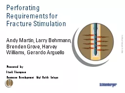
Andy Martin Larry Behrmann Brenden Grove Harvey Williams Gerardo Arguello Presented by Frank Thompson Business Development Mgr North Europe Agenda Perforating o bjectives for ID: 468193
Download Presentation The PPT/PDF document "Perforating Requirements for Fracture St..." is the property of its rightful owner. Permission is granted to download and print the materials on this web site for personal, non-commercial use only, and to display it on your personal computer provided you do not modify the materials and that you retain all copyright notices contained in the materials. By downloading content from our website, you accept the terms of this agreement.
Slide1
Perforating Requirements for Fracture Stimulation
Andy Martin, Larry Behrmann, Brenden Grove, Harvey Williams, Gerardo ArguelloPresented by: Frank ThompsonBusiness Development Mgr North EuropeSlide2
Agenda
Perforating objectives for fracture stimulationEffect of perforating parametersHorizontal wellsConclusionsSlide3
Perforating Objectives for Fracturing
Make
frac
jobs more effective
Lower
breakdown pressures
Lower treatment pressures with better
treatment rates
Controlled
frac
placement
All
of this leads to better
production
Also
helps avoid disasters like aborted
jobsSlide4
Perforating Objectives
Perforations should minimize:Near wellbore pressure drop Perforation friction
Tortuosity
Micro-annulus pinch points
Multiple competing
fracturesSlide5
What can we control?
Size and type of gunPenetration (type of charge)Casing entrance holeShot densityShot phasing
Interval length
Gun orientationSlide6
Casing Entrance Hole
EH size about 8 to 10 times proppant diameter to prevent bridgingConsistent EH for accurate limited entry designs40% variation in EH results in 120% increase in pressure drop
(from SPE 83590)
EH variation
Error in pressureSlide7
Minimizing Casing Entrance Hole Variation
Use largest gun possible to reduce water clearanceCentralize gun Design shaped charge for minimum variation even across large water clearances
Std
Frac charge
New Frac charge
Best Frac ChargeSlide8
Is Penetration Important ?
Sometimes ignored (we just need some holes in the casing)What about near wellbore conditions?breakoutsformation damage?near wellbore stress?Frac experts starting to realize that penetration is a benefit (>1 BH)Connection to the far field helps avoid near-wellbore tortuosity effects
Up to 5-inch damage (SPE 112862)Slide9
What about Clean Perforations?
Enable injection to start deeper in formation, avoids near wellbore damaged zoneFractures may not initiate from plugged perforations (see “big block” tests left)Clean perforations allow fluid leak-off, increasing near-wellbore pressure prior to fracture initiation
(from SPE 143997)
Plugged perforations NO fracture
Clean Perforations with fracture passing through perforations
(from SPE
20661
)Slide10
Plugged
perfs
NO fracture
(from SPE
20661
)Slide11
Clean
Perfs
Fracture
(from SPE
20661
)Slide12
Gun Phasing and Direction
Near-vertical wellsFractures initiate from perforations aligned with maximum stress directionBest gun phasing is 0° – 180° in max stress direction
Perforations aligned with maximum horizontal stress
(from SPE
20661
)Slide13
Perforations aligned with maximum horizontal stress
(from SPE
20661
)Slide14
Fractures initiate from sand-face when perforations are misaligned
Other gun phasings: 120° (at 1 ½ times spf); 60° (at 3 times spf)
Perforations misaligned with maximum horizontal stress
(from SPE
20661
)
Gun Phasing and Direction
Near-vertical wellsSlide15
Perforations
not
aligned with maximum horizontal stress
(from SPE
20661
)Slide16
Well Direction and Gun Phasing
Gun phasing and interval perforated should be based on well direction compared to the preferred fracture planeSlide17
Hydraulic Fractures in Horizontal Wells
What we want
Transverse
fracs
Longitudinal
fracsSlide18
What We Get
with 60° Phasing
Longitudinal fractures initiate first
T
erminate about 2 wellbore diameters in vertical direction
E
xtend along wellbore
Initial
pumped volumes dominated by longitudinal
fracs
Transverse fractures initiate after
P
erpendicular to longitudinal
D
o not rotate from longitudinalSlide19
What we getwith
60° PhasingSlide20
Can We Do Better?
Several experiments done in large blocks in a tri-axial stress frame to simulate horizontal wellBoth
DP and BH charges used
Directional perforations aimed at the same transverse
plane
Transverse fracture from directed perforations
Result
:
Transverse
fractures createdSlide21
Directional perforations
in the same transverse planetransverse fractures are createdSlide22
Perforation Gun Length-Horizontal Wells
In horizontal wells perforation length should be limited to about 2 to 4 times the wellbore diameter (ref SPE 19720)
Minimizes multiple competing fractures
Typical gun contains 6 to 10 shots (60° phased)
2 to
4
guns are shot for each
frac
stage
G
uns run with addressable switches in
pumpdown
plug-n-
perf
modeSlide23
How Many Clusters per Stage?
Closely spaced clusters increases flow rate in gas shalesTrade off is cost (number of fractures vs production
)
SPE 144326 shows study on production
vs
clusters for major shale plays
Reducing the number of clusters
increases
odds of all clusters being
stimulated
48% of
perf
clusters aren’t contributing in wells having 6 or more
perf
clusters
/
frac
stage
Cluster placement should be matched to reservoir quality
Requires detailed modeling
SPE 146872 and SPE 146876 detail modeling work flowSlide24
Horizontal shale well production log analysisSlide25
Conclusion
Well planned perforating will make frac jobs more effectiveCareful choice of shaped charges, gun phasing and orientation will help initiate fractures and minimize tortuosityIn horizontal wells selection of number of shots, position of clusters impacts well productivitySlide26
Questions?