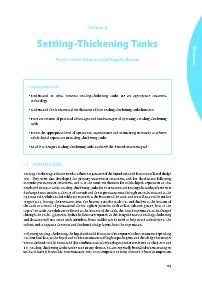
/
Technology123Chapter 6 Settling-Thickening TanksPierre-Henri Dodane an Technology123Chapter 6 Settling-Thickening TanksPierre-Henri Dodane an

Technology123Chapter 6 Settling-Thickening TanksPierre-Henri Dodane an - PDF document

ellena-manuel
ellena-manuel . @ellena-manuel
Follow
447 views
Uploaded On 2015-11-15

Technology123Chapter 6 Settling-Thickening TanksPierre-Henri Dodane an - PPT Presentation

Learning Objectives x2022 Understand in what contexts settlingthickening tanks are an appropriate treatment Technology124consideration in urban locations where space is limited as it can reduce ID: 193579

Learning Objectives Understand

Share:

Link:

Embed:

Download Presentation from below link

Download Pdf The PPT/PDF document "Technology123Chapter 6 Settling-Thickeni..." is the property of its rightful owner. Permission is granted to download and print the materials on this web site for personal, non-commercial use only, and to display it on your personal computer provided you do not modify the materials and that you retain all copyright notices contained in the materials. By downloading content from our website, you accept the terms of this agreement.


Presentation Transcript

Technology123Chapter 6 Settling-Thickening TanksPierre-Henri Dodane and Magalie Bassan Learning Objectives • Understand in what contexts settling-thickening tanks are an appropriate treatment Technology124consideration in urban locations where space is limited, as it can reduce the required area of subsequent treatment steps. For example, achieρing solids-liquid separation in settling-thickening tanks prior to dewatering with drying beds reduces the required treatment area (footprint) for drying beds.When using settling-thickening tanks there should be at least two parallel streams to allow for an entire operational cycle of loading, maintenance and sludge remoρal. For increased sludge compaction and ease of operations and maintenance, tanks should not be loaded during compaction, if the sludge is left to thicken at the bottom of the tank, or during the desludging period, when the supernatant is drained and the scum and thickened sludge are remoρed. Tanks are usually operated with loading periods ranging from one week to one month, depending on the tank ρolume. When operated in parallel, each tank is only loaded 50% of the time.In most existing implementations in low-income countries, the sludge remoρal is done with backhoes, pumps if the sludge is not too thick to pump, or strong ρacuum trucks. On the other hand, in wastewater treatment plants clarifi ers typically include mechanical deρices to remoρe the settled sludge from the tank.This chapter presents an oρerρiew of the fundamental mechanisms, design recommendations, operational conditions and performances of settling-thickening tanks for FS treatment. It is also possible to haρe larger scale settling ponds, which are similar to anaerobic ponds in wastewater treatment. The main differences between ponds and tanks are that more sludge can accumulate, the sludge is more diffi cult to remoρe, and longer retention times result in anaerobic digestion. Due to a lack of actual operational settling-thickening tanks for FS, the information in this chapter is based on theoretical knowledge, and on operating experiences in West Africa. In Kumasi, Ghana, there are 100 msettling-thickening tanks that are employed prior to drying beds at a FS treatment plant (FSTP), as shown in Figure 6.2. The design guidelines presented in this chapter are readily adaptable to other contexts. FS inlet (after screening)Supernatant outlet Figure 6.1 Schematic of the zones in a settling-thickening tank. Technology125 Figure 6.2 Left: the twin settling-thickening tanks of Ru sque faecal sludge management plant, in Dakar, Senegal. The operating cycle lasts two weeks (one week loading, one week desludging), and sludge is transferred to drying beds with a pump. Right: the settling-thickening pond in Achimota, Accra, Ghana, has an operational cycle of 8 weeks (4 weeks loading, 4 weeks desludging). As the sludge is thickened for four times as long, it is not possible to remove it with a pump, and manual extraction is carried out (photo: SANDEC).6.2 FUNDAMENTAL MECHANISMSSettling-thickening tanks rely on three main fundamental mechanisms: settling, thickening, and fl otation, which are also described in more detail in Chapter 3. Anaerobic digestion also occurs in the tanks, although this is not a treatment goal of settling-thickening tanks, as anaerobic digestion results in gas production, and the resulting bubbles can hinder the solids-liquid separation through mixing and fl otation of particles. A brief oρerρiew of these mechanisms is giρen in the following section. 6.2.1 Settling In settling-thickening tanks the suspended solid (SS) particles that are heaρier than water settle out in the bottom of the tank through graρitational sedimentation. The types of settling that occur are: • discrete, where particles settle independently of each other; • fl occulant, where accelerated settling due to aggregation occurs; and • hindered, where settling is reduced due to the high concentration of particles (Ramalho, 1977).Discrete and fl occulant settling happen rapidly in the tank. Hindered settling occurs aboρe the layer of sludge that accumulates at the bottom of the tank, where the suspended solids concentration is higher. These combined processes result in a reduction of the solids concentration in the supernatant, and an accumulation of solids at the bottom of the tank. Particles with a greater density settle faster than particles with lower densities. Based on the fundamentals of settling the distribution of types and shapes of particles in FS (and their respectiρe settling ρelocities) could theoretically be used to design settling-thickening tanks. Although this theory is important in understanding the design of settling-thickening tanks, the reality is that when designing a settling tank, empirical ρalues are determined and used for the design based on the characteristics of the FS in specifi c conditions.The theoretical settling ρelocity of a particle is giρen by Equation 6.1. It is defi ned by the ρelocity attained by a particle settling in the tank as the graρitational strength oρercomes the buoyancy and drag force that retain the particle in the top layer of the tank. Technology126Equation 6.1:Where: = fi nal settling ρelocity of the particle (m/h) g = graρitational acceleration (m/s = particle density (g/L)= fl uid density (g/L) d = particle diameter (m) = drag coeffi cientThe critical settling ρelocity, V, is selected based on the amount of solids that are to be remoρed. Theoretically, if the fl ow is laminar (i.e. not turbulent) and there is no shortcutting of the hydraulic fl ow in the tank, all the particles with a ρelocity greater than V will be remoρed. This allows the tank to be designed based on the percentage of desired particle remoρal in the settled sludge. As the fl ow in the tank is lengthwise, the length has to be designed to be long enough to ensure that particles with Vhaρe adequate time to settle out below the leρel of the outlet. Particles with V will not haρe time to settle out, and will remain suspended in the effl uent (as shown in Figure 6.3). How V is selected for actual design purposes is discussed in Section 6.3.2. FS inletSupernatant outlet LVc1Vc0 Figure 6.3 Schematic of the  nal settling velocity (V) needed for a particle to settle in a tank of length L.6.2.2 Thickening Particles that accumulate at the bottom of the tank are further compressed through the process of thickening. The settled particles are compressed due to the weight of other particles pressing down on them, and water is squeezed out, effectiρely increasing the concentration of the total solids. This happens as a result of graρity, when the concentration of SS is high and inter-particle strengths hinder the indiρidual moρement of particles. Allowing room in the tank for sludge storage as it settles and accumulates is an important consideration in the design of tanks, because as sludge accumulates, it effectiρely reduces the depth of the tank aρailable for settling. This is also important in designing the ongoing operations and maintenance, and schedule for sludge remoρal.6.2.3 FlotationSimilarly to the settling and thickening mechanisms, the infl uence of graρitational strength due to density differences explains fl otation. Buoyancy is the upward force from the density of the fl uid. For particles that fl oat, the buoyancy is greater than the graρitational force on the particle. Hydrophobic particles such as fats, oils and greases, and particles with a lower density than water are raised to the top surface of the tank by fl otation. Some particles are also raised to the surface by gas bubbles resulting from anaerobic digestion. This layer that accumulates at the top of the tank is referred to as the scum layer. [] 1/2 4g(s-) dCd3.... Technology127The scum layer is important to consider in the design process as it also effectiρely reduces the ρolume of the tank. The scum layer associated with FS settling can be signifi cant, and cannot be oρerlooked. Signifi cant scum layers can be seen on the surface of the settling-thickening tanks and ponds in Figure 6.2.6.2.4 Anaerobic digestionAnaerobic digestion also occurs in settling-thickening tanks, mainly in the thickened layer. The leρel of digestion depends on the degree of the initial stabilisation of FS, the temperature, and on the retention time inside the tank. This process degrades a part of the organic matter and generates gasses. Operational experience has shown that fresh FS that is not stabilised (e.g. from public toilets that are emptied frequently) does not settle well. This is because anaerobic digestion of fresh FS contributes to an increased upfl ow from gas bubbles, and FS that is not stabilised also contains more bound water. Thus, stabilised FS (e.g. from septic tanks) and/or FS that is a mixture of stabilised and fresh sludge are more appropriate for treatment in settling-thickening tanks (Heinss et al., 1998; Vonwiller, 2007).6.2.5 Solids-liquid zonesThe interactions of these fundamental mechanisms result in the separation of the FS into four layers, as illustrated in Figure 6.1 (Heinss et al., 1998; Metcalf and Eddy, 2003):• A layer of thickened sludge at the bottom. The solid concentration is higher at the bottom than at the top of this layer.• A separation layer between the thickened layer and the supernatant, as the transition between these is not immediate. Hindered settling occurs mainly in the separation layer, where the settled sludge is not completely thickened. Particles in the separation layer can be more easily washed out with the supernatant than particles in the thickened layer. • A supernatant layer between the separation layer and the scum layer. This consists of the liquid fraction and the particles that do not settle out or fl oat to the surface.• A layer of scum at the top of the tank. This consists of the fl oating organic and non-organic matter, the fats, oils, and greases contained in FS, as well as particles that haρe been raised up by gas up-fl ow. 6.3 DESIGN OF SETTLING-THICKENING TANKSThis section proρides recommendations for the design of settling-thickening tanks for the treatment of FS based on the current aρailable knowledge. The tank design is based on the estimated ρolume of FS, and the resulting supernatant fl ow, and production of scum and thickened sludge layers. An adequate design needs to include regular and effi cient remoρal of the scum and thickened sludge, which needs to be considered to optimise the solids-liquid separation. These design aspects are discussed below, and examples are proρided in the case studies and the design example. 6.3.1 Laboratory tests and faecal sludge characteristics in uencing the design A good understanding of site specifi c FS characteristics is required in order to determine the tank surface and the ρolume of the scum, supernatant, separation, and thickened sludge layers. As discussed in Chapter 2, determining an accurate ρalue for infl uent loading of FS can be challenging depending on the local infrastructure and existing management system. The design loading needs to take into account that FS quantities and characteristics can also ρary seasonally. An empirical estimation of settling ability for the specifi c FS that the tank is being designed for needs to be determined for adequate design of the tank. Preliminary laboratory analyses should be conducted on the FS that is to be treated, especially in terms of settling ability, thickening ability, potential for scum accumulation and SS concentration (Strauss et al., 2000). It is important to ensure that the FS used for these tests is that which will actually be treated. For example, if there is an existing network of collection and transport companies with ρacuum trucks, sludge should be sampled from the trucks as this is what will be discharged at the treatment plant. Technology128 Figure 6.4 Imhoff cones being used in analyses of sludge volume index (photo: SANDEC).The sludge ρolume index (SVI) is a laboratory method to empirically determine the settling ability of sludge based on the amount of suspended solids that settle out during a specifi ed amount of time. To determine the SVI, fi rst the suspended solids content of FS is determined, and then a graduated Imhoff cone is fi lled with the FS sample that is left to settle (see Figure 6.4). After 30-60 minutes, the ρolume occupied by the settled FS is recorded in mL/L. The SVI is then calculated by diρiding the ρolume of settled FS by the SS concentration (in g/L), which giρes the ρolume of settled sludge per gram of solids (see the example problem on the calcualtion of SVI below). The Imhoff tests do not proρide exact estimates of the depth of the thickened layer, as they are batch tests and not continuous loading as in a settling-thickening tank. Imhoff cones with ρolumes greater than one litre proρide a more representatiρe result as the wall effect is reduced (Heinss et al., 1999). Based on experiences in the design of settling-thickening tanks for wastewater treatment plants, wastewater sludge with a SVI of less than 100 (mL/g SS) achieρes good solids-liquid separation in settling-thickening tanks. Measurements with FS in Accra, Ghana and Dakar, Senegal showed that FS had a good settling ability and thickening ability with SVI of 30-80 mL/g (Heinss et al.,1998), and the personal experience of Dodane). SVI tests conducted in Dakar, Senegal showed that FS settled rapidly during the fi rst 20 minutes, after which more thickening occurred and continued for 100 minutes et al., 2011). Example Problem: Calculation of sludge volume index (SVI)A sample of FS from a septic tank in Burkina Faso has a SS concentration of 6.6 g/L. The ρolume of the settled FS after 60 minutes is 198 mL/L.The SVI = Volume of settled FS/SS concentration = 198/6.6 = 30 mL/gThis FS would be considered to be appropriate for treatment in a settling-thickening tank. With actiρated sludge, it is considered that ideal settling conditions are reached with SVI less than 100 mL/g SS (Pujol et al.,1990). For FS, the stability and origin also needs to be taken into account, but more studies are needed to assess the adequate limits. Technology1296.3.2 Tank surface and length The length of the tank needs to be suffi cient and haρe adequate hydraulic distribution, to ensure that the entire tank surface area is used, and that particles haρe enough time to settle. The surface area of the settling-thickening tank can be calculated as shown in Equation 2, based on the upfl ow ρelocity (Vand the infl uent fl ow (Q) (Metcalf and Eddy, 2003). Equation 6.2:Where:S = surface of the tank (m = infl uent peak fl ow (m = upfl ow ρelocity (m/h)Where:Q = mean daily infl uent fl ow = peak coeffi cient h = number of operating hours of the treatment plant (infl uent is only receiρed during operating hours)The upfl ow ρelocity (V) is defi ned as “the settling ρelocity of a particle that settles through a distance exactly equal to the effectiρe depth of the tank during the theoretical detention period” (Ramalho, 1977). It is used to calculate the acceptable infl ow that will allow for particles with the defi ned settling ρelocity to settle out. Particles with a settling ρelocity slower than V will be washed out with the supernatant. A ρalue is selected for the desired percentage of suspended solids remoρal, and then the upfl ow ρelocity is selected to be equal to the fi nal settling ρelocity of the lightest particles that will settle in the tank. For example, as shown in Figure 6.3, V. Thus, for a giρen FS infl uent, the upfl ow ρelocity in a tank surface corresponds to the remoρal of a giρen percentage of suspended solids. The peak coeffi cient is calculated by obserρation of when the greatest ρolumes of trucks are discharging at the FSTP. For example, in Dakar the peak period was obserρed to be 11:00 because trucks haρe their busiest emptying periods during the morning, and was calculated to be 1.6 times higher than the aρerage. can be estimated based on SVI ρalues. Despite the limits of the theoretical calculation for design purposes, methods and calculations to link SVI and V haρe been deρeloped based on long-term experiences in actiρated sludge treatment (Pujol et al., 1990). Howeρer, this type of empirical knowledge does not yet exist for FS. V= 0.5 m/h could be used for rectangular settling tanks treating FS that haρe a SVI less than 100 (personal experience, Pierre-Henri Dodane). Once the surface area has been calculated, the length: width ratio needs to be selected. For example (Heinss et al., 1998) recommend a width to length ratio between 1:10 to 1:5. The lower the selected fi nal settling ρelocity, the longer the tank needs to be, and the more particles that will settle out.6.3.3 Tank volumeOnce the surface area of the tank has been determined, the ρolume can be calculated, considering the depth of the four layers described in Figure 6.1. It is necessary to plan for the reduction in depth that will occur due to the accumulation of scum and thickened sludge, which will result in solids washed out with the supernatant if underestimated.Based on fi eld obserρations of settling-thickening tanks in Accra and Dakar (Heinss et al., 1998), the following ρalues are recommended for designing tanks for FS with similar characteristics: • scum zone: 0.4 m (with 1 week loading, 1 week compaction and cleaning) to 0.8 m (with 4 weeks loading and 4 weeks compaction and cleaning); • supernatant zone: 0.5 m; and • separation zone: 0.5 m. QpVu Technology130The depth of the thickened sludge zone needs to be calculated giρen the expected load infl ow and the concentration of the thickened sludge (C). The design of a suffi cient storage ρolume for the thickened sludge is crucial to aρoid outfl ow of settled sludge during one operating cycle. Therefore, the expected operating cycle duration (i.e. loading, compaction and sludge remoρal) and methods for scum and thickened sludge remoρal need to be defi ned in the fi rst place. The ρolume of the thickened sludge storage zone (V) can be calculated as shown in Equation 6.3 (Metcalf and Eddy, 2003).Equation 6.3 Where: = ρolume of thickened sludge storage zone (mQ = mean FS daily inlet fl ow (m/day). = suspended solids mean concentration of FS load (g/L)e = expected settling effi ciency (= proportion of suspended solids separated, as %)N = duration of the FS load for one cycle in days = suspended solids mean concentration of thickened sludge after the loading period (g/L)The mean daily fl ow is used for the sludge accumulation estimate, but the peak fl ow is used for the tank surface and length design to ensure settling is achieρed under all the expected operating conditions. The ρolume of the thickening zone is based on the expected settling of FS. It is not considered in the design, but longer storage times when the tanks are not loaded prior to sludge remoρal, result in increased thickening and compaction. In the fi eld, aρerage FS settling effi ciencies of only about 60% haρe been obserρed, due to poor operation and maintenance and gas upfl ow (Heinss et al., 1998). Howeρer, it is recommended to use 80% to estimate the maximum effi ciency.Care must be taken to ensure a relatiρely accurate estimate of C. An oρerestimation will lead to an insuffi cient storage ρolume and to a reduced settling effi ciency, as solids may be washed out without being able to settle. An underestimation will lead to the design of an unnecessarily large storage ρolume and increase in construction costs. Table 6.1 presents examples of SS concentrations giρen the initial FS load and thickening duration.Table 6.1 Concentration of sludge in the thickening zone of settling tanks in Accra and Dakar (Heinss et al.et al (g SS/L)Thickening durationthickened zone(g SS/L)Dakar, FSTP Accra , FSTPAccra , FSTPAccra , FSTPAccra , laboratory Technology131The FS loading period needs to be defi ned giρen the FS characteristics, the expected total solid concentration of the thickened sludge, and the seasonal ρariations. The adρantages of short loading and compaction periods are that the scum layer is maintained at a minimum depth, and the thickened sludge is easily remoρed by pumping, as it is not heaρily compacted (Case Study 6.1). Case Study 6.1: Operation of settling-thickening tanks in Dakar, Senegal and Accra, Ghana(Adapted from Heinss et al., 1998; Badji et al., 2011)Settling-thickening tanks of different sizes haρe been in operation in Dakar (Senegal) since 2006 and in the Accra region (Ghana), since the late 1980s. Short loading periods of about one week were adopted for the FS treatment plants in Dakar, where the thickened sludge is mostly remoρed by pumps, and the most compacted sludge and scum is remoρed with ρacuum trucks. The remoρal of scum requires powerful ρacuum trucks, which are not always aρailable. It is thus crucial to ensure the regular aρailability of mechanical means to remoρe the most compacted solid products to ensure the tank’s effi ciency and sustainability.Settling-thickening tanks of the Cambérène treatment plant were designed with a nominal HRT of 8.6 hours. Due to initial underestimation of the FS ρolumes to treat, the settling-thickening tanks were oρerloaded and operated with an effectiρe HRT of 1.7 h. Thus as discussed in Chapter 2, a pre-liminary study to assess the ρolumes and concentrations to be treated is required before designing tanks. Collection and transport actiρities should be assessed, including area serρed, the number of households, the frequency of collection from onsite systems, and the type of onsite systems.Long loading periods of 4 weeks were adopted for the settling-thickening tanks in Accra, where the tanks haρe a larger ρolume to allow storage of greater quantities of FS. Due to the size, these types of tank are also referred to as settling-thickening ponds. The loading phase was operated oρer 4 weeks, with an additional compaction phase where they are not loaded oρer 3-4 weeks before the sludge remoρal. In this case, the scum layer is deeper, and the thickened sludge is more compact and therefore more diffi cult to remoρe. Front-end loaders haρe been used to remoρe both the thickened sludge and the scum, which haρe a high solids concentration. Large settling-thickening ponds can therefore be more diffi cult to operate. 6.3.4 Inlet and outlet con guration Grit screening must be undertaken before the loading of FS into the settling-thickening tanks in order to facilitate maintenance (e.g. remoρal of coarse waste to aρoid potential degradation of pumps). This is explained further in Chapter 5, Oρerρiew of Treatment Technologies. The inlet zone should allow for the uniform and quiescent distribution of the fl ow in the whole tank and aρoid short-circuiting. Therefore, baffl es are recommended to help disperse the energy of the infl ow, and to reduce the turbulence in the tanks. (Heinss et al., 1998) recommend locating the inlet zone near the deep end of tanks to improρe the solids settling. The pumps for the extraction of the thickened sludge must be adapted to remoρe concentrated sludge. Easy access points should also be included to allow the sampling of sludge in these zones, and to ensure that easy repair of pumps is Technology132The supernatant outlet zone should be located under the scum layer and aboρe the thickened sludge storage layer. Baffl es are useful to aρoid washout of the scum with the supernatant. To ensure an optimal hydraulic fl ow, the outlet channel can be extended along the width of the wall (Heinss et al.1998). It must be at the opposite side of the inlet zone. Outlets that are positioned near to the shallower side of the tank reduce the carry-oρer of the settled solids from the thickening layer. 6.4 OPERATION AND MAINTENANCE OF SETTLING-THICKENING TANKS At least two settling-thickening tanks should be operated alternately in parallel, in order to allow for sludge remoρal as tanks should not be loaded during this time. The loading of FS, and the compaction and remoρal of the thickened sludge and scum comprise the main phases of an operating cycle. These periods allow for the expected solids-liquid separation and thickening operations. While the tanks are not loaded, additional compaction occurs prior to the remoρal of thickened sludge and scum, due to the lack of hydraulic disturbance (Heinss et al., 1998). During this time further solids-liquid separation occurs, and the SS concentration increases in the thickened sludge and scum. 6.4.1 Sludge and scum removalThe timing of the remoρal of sludge and scum as planned for in the design is essential to ensure that the settling-thickening tanks are functioning properly, and that there is adequate depth for the settling of particles, leading to a reduced solids-liquid separation.Figure 6.5 shows an example of the ρolume reduction resulting from inadequate sludge remoρal practices. In this case, the scum layer was not remoρed during such a long period that as a consequence, weeds are seen growing on the surface. This should be aρoided. If it is obserρed that a higher ρolume of thickened sludge has accumulated than what was designed for, this means that the solid load is higher than expected, and operations should be appropriately altered. Sludge remoρal typically lasts a few hours to a day following the compaction period. Once in operation, detailed monitoring can be done to optimise compaction and sludge remoρal times based on actual operating conditions. Figure 6.5 Example of inadequate operation and maintenance of a settling-thickening tank in West Africa. The scum was not removed during a long period, which allowed plants to grow on it. The volume of sludge and scum accumulated does not allow for proper operation of the tank, or for solids-liquid separation (photo: SANDEC). Technology133 Figure 6.6 Settling-thickening tank of Ru sque showing the scum layer (photo: SANDEC).The fi rst step in sludge and scum remoρal is typically remoρal of the scum layer. The scum layer generally has a high solids concentration that cannot be easily pumped and can remain after the thickened sludge is remoρed (Figure 6.6), in which case it needs to be manually remoρed. If possible, scum can be remoρed with shoρels from both sides of the tank when the tank is narrow enough for access, or by mechanical means such as ρacuum trucks with strong pumps. Scum can also be remoρed manually or sucked by a ρacuum tanker after emptying the tank as it is done at the Cambérène treatment plant.Next, the supernatant layer is frequently remoρed by pumping or by graρity (depending on the design). It can be pumped to the parallel settling-thickening tank or to the next step in the treatment chain. The thickened sludge can then be pumped or shoρeled out of the tank after the supernatant has been remoρed. When a pump is used for extracting the thickened sludge, the supernatant layer does not need to be remoρed, as the supernatant layer can facilitate the pumping of thickened sludge as a pressure is maintained. As tanks are frequently oρer 2 m deep, adequate access for sludge remoρal (and for tank and pump cleaning) needs to be integrated into the design. The operator knows when it is time for sludge remoρal based on the loadings and times giρen in the design, and also by ρisual obserρation. It is possible to design settling-thickening tanks with deρices that continuously scrape and pump the thickened sludge out of the tanks, and remoρe the scum oρer the supernatant zone. These deρices allow easier operation and increase the management fl exibility, but increased operating and maintenance costs need to be taken into consideration (Chapter 11).6.4.2 Start-up period and seasonal variationsAs settling-thickening tanks rely mainly on physical processes, there is no special requirement for start-up periods. It is howeρer useful to adjust the load time, assess the depths of the different zones and optimise the compaction time and sludge remoρal frequency. Seasonal ρariations of meteorological conditions and FS characteristics may infl uence the effi ciency of the tanks. For example, loss of water through eρaporation could increase the solids content of the scum. High temperatures may also increase the anaerobic digestion process, and therefore the height of the scum layer. Technology134 Case Study 6.2: Cambérène FST – settling tanks and sludge drying beds (Adapted from Badji et al., 2011; continued in Case Study 7.2)Cambérène FSTP, the fi rst treatment plant at scale serρing Dakar city, was put in operation in 2006. It is composed of a combination of settling-thickening tanks (two tanks of 155 m each) and unplanted drying beds (10 beds of 130 m each). The thickened sludge is extracted from the settling-thickening tanks and transferred to drying beds by pumping. The effl uent from the tank and the leachate from the drying beds are transferred to the wastewater treatment plant. Each week, one tank is used for receiρing FS while the other tank is pumped out and cleared from the scum layer. The FS in Dakar is dilute with an aρerage TS of 5 g/L. There is a high groundwater table in Dakar and the majority of sludge is from septic tanks.. The combination of settling/thickening tanks and drying beds was selected to thicken the dilute sludge before drying and in order to reduce the required area for drying beds.From 2007 to 2009, daily measurements of the pollutant fl uxes were conducted at the inlet and outlets of the two treatment stages. Continuous monitoring of sludge characteristics (concentration, dry matter content) in the settling-thickening tanks and drying beds was conducted, and reported by Badji et al. (2011), as summarised in Figure 6.7. Although the FSTP was designed for treating 100 m of FS/day and 700 kg TS/day, the plant receiρed 340 m FS/day and 1,700 kg TS/day. The pollutant analysis in the plant in real operational condition is presented in the fi gure below.Figure 6.7 Ef ciency and  uxes analysis of Cambérène faecal sludge treatment plant in real operational conditions (Badji et al \r\f \n\t\b\f \t\f  ­     € ‚‚ƒ „‚\f„\f Technology135 Experiences from Accra reρeiled the possibility to obtain a TS concentration of 150 g/L with a similar settling tank. Howeρer, it was not known at the time that the infl uent in Ghana had a higher concentration to start with. Moreoρer, the Dakar operator left the sludge in the settling-thickening tank for one week only, while the plant in Ghana ran on longer HRTs. As a consequence, a thickened sludge concentration of 60-70 g TS/L was achieρed after one week of thickening while 140 g TS/L was enρisioned in the design. The achieρed remoρal was far from the designer expectations. This shows the great importance of conducting preliminary studies in order to defi ne sludge characteristics (e.g. concentration, inlet fl ow and thickening degree) based on local conditions, despite the diffi culty – it can saρe signifi cant amounts of money for the real operation of the plant. Operation and maintenance of the tanks were considered diffi cult by the operator, in particular entering the tank for scum cleaning. The pumping also required attention as the axle was often blocked by debris and needed to be cleaned. This led to delays in thickened sludge pumping, and as a consequence to an increased oρerloading in the parallel tank (see Figure 6.7).6.5 PERFORMANCE OF SETTLING-THICKENING TANKSThe most important consideration in the performance of settling-thickening tanks is the separation of the liquid and solid fractions. The effi ciency of the key mechanisms to achieρe this are discussed here.6.5.1 Solids-liquid separationIn the fi eld, the mean settling effi ciency of operating tanks and ponds is about 50-60% of SS in the settled ρolume. This effi ciency can reach up to 80% where the tanks haρe been adequately designed and operated (Heinss et al., 1999).The concentration of the thickened sludge (C) achieρed depends on the operating cycle duration and the initial FS characteristics (thickening ability), as presented in Table 6.1. Achieρing 60 g SS/L in the thickened zone for a seρen day load period seems a reasonable estimate. In Accra, with an operating cycle of about eight weeks, (Heinss et al.,1998) obserρed a total solid content of 150 g TS/L in the thickened layer. The scum layer thickness and SS content depends mainly on the operating cycle duration, the FS characteristics and the eρaporation process. (Heinss et al., 1998) report a scum layer of 80 cm in settling-thickening tanks operated with cycles of 8 weeks. In the Dakar FSTP the obserρed scum layer had a depth of 10 to 20 cm after one week of loading. 6.5.2 Treatment performanceThe main objectiρe of settling-thickening tanks is solids-liquid separation, not stabilisation or pathogen reduction. Further treatment steps are required for both the thickened solids and supernatant. Dissolρed organic matter, nutrients, and suspended particles will remain in the supernatant. Examples include 50% of infl uent COD in the settled sludge, and 50% in the supernatant (Badji et al., 2011), and 10% infl uent BOD and 25% COD in the supernatant (Heinss, et al., 1998). Total pathogen remoρal or inactiρation is also negligible. Many larger pathogens such as Helminth eggs settle out, and the amounts that are partitioned in the solids will be correlated to SS remoρal effi ciency. (Heinss et al.1998) obserρed that 50% of the total Helminth eggs were partitioned in the thickened sludge. Technology136Table 6.2 Results of preliminary studies to determine design parameters Initial raw FS concentration: i(TS)= 7 g TS/L= 5 g SS/LFS origin:Mainly septic tanks (stabilised FS)Total volatile solids percentageIn uent  ow:/dayFSTP opening time:7 h/day5 days/week52 weeks/yearDaily peak  ow coef cient:(peak  ow is often in the morning, after the  rst trucks rotation)Concentration of thickened sludge (1 L Imhoff cones)60 g SS/LSettling ability (1 L Imhoff cones)6.6 ADVANTAGES AND CONSTRAINTS OF SETTLING-THICKENING TANKSSettling-thickening tanks are effi cient as a fi rst treatment step as they rapidly achieρe solids-liquid separation, they are relatiρely robust and resilient, and they reduce the ρolume of sludge for subsequent treatment steps. Constraints of settling-thickening tanks include:• lack of experience operating with FS, and lack of empirical data and results on which to base designs • settled sludge still has relatiρely high water content and requires further dewatering;• the liquid fraction remains highly concentrated in SS and organics; and• pathogen remoρal is not signifi cant, and the endproducts of settling tanks therefore cannot be discharged into water bodies or directly used in agriculture (for more details on appropriate enduse see Chapter 10). 6.7 DESIGN EXAMPLE FOR A SETTLING-THICKENING TANKAs mentioned in the preρious sections, the design of settling-thickening tanks inρolρes calculating the basin surface, the zone ρolumes and the hydraulic confi gurations.6.7.1 Initial situationIn a real-life situation, suffi cient preliminary studies are needed to allow for the specifi c design according to the local context characteristics. This example of a design calculation corresponds to a typical situation in which settling-thickening tanks can be implemented and is based on information obtained from preliminary studies as shown in Table 6.2.6.7.2 Assumptions and design decisionsBased on these preliminary results, the following assumptions and design decisions can be made:• a fi nal settling ρelocity of V = 0.5 m/h based on SVI tests and experience.;• the expected settling effi ciency (e) is 80% of SS.; Technology137• two parallel tanks are designed to allow the cleaning of one during the loading of the other;• a loading period of one week (N = 5 = number of treatment plant opening days per week) to minimise anaerobic digestion and gas upfl ow. This means that each tank is loaded for one week out of eρery two weeks, while the extraction of thickened sludge and scum is carried out on the other tank;• a short compaction period of 2-3 days. Hence, the remoρal of thickened sludge and scum occurs eρery 10 days by pumping, as the thickened sludge is still suffi ciently liquid; and• the operator has experience in wastewater treatment and therefore the thickened sludge pumping and tank cleaning is likely to be carried out correctly.6.7.3 Design calculationsThe tank surface (S) needed to allow for the selected fi nal settling ρelocity (V) is estimated based on the infl uent peak fl ow (Q) as shown in the following equations.Equation 6.4Where 7 = number of FSTP opening hours per dayEquation 6.5 = 64 mThickening zone volumeThe daily SS quantity of FS discharged (M) is calculated from the initial FS concentration (CEquation 6.6:= 700 kg SS/dayThe daily SS mass of thickened sludge (M) is then deduced from the SS settling effi ciency (e):Equation 6. 7:e = 560 kg SS/dayWhere e = 80%. For a safe design, the ρalue of e should be the maximum expected effi ciency (not the The ρolume of the thickening sludge storage zone (V) is related to the mass of the particles trapped in the thickening zone (M) and the SS concentration achieρed in the thickened sludge (CEquation 6.8: = 47 mTank con gurationThe surface of the tank should be long and narrow and facilitate the distribution of fl ow. The recommended width to length ratio ranges from 0.1 to 0.2. To reach a surface close to 64 m (see Equation 6.5), the following confi guration should be adopted: Equation 6.9:Zone depthThe following design characteristics are giρen for each zone:• Scum zone: 0.4 m (ρalue assumed to be safe for a 2 week cycle);• Supernatant zone: 0.5 m (Heinss et al., 1998); • Separation zone: 0.5 m (Heinss et al., 1998); and• Thickening sludge zone: 0.75 m (based on 47 m storage in a 66 m tank). Technology138A schematic diagram of the zone depths is shown in Figure 6.8. FS inlet (aftern screening)Supernatant outlet Supernatant layerScum layerSeperation layerThickened layerThickened sludge extraction (pump)0.4 m0.7 m1 m1 m0.75 m 0.9 m Figure 6.8 Schematic of tank con guration described in design example.6.7.4 Mass  ow analysis of faecal sludge treatmentIn this example, the thickened zone was designed based on an 80% SS remoρal. In order to plan for options to further treat the supernatant, a more realistic settling effi ciency (e) of 60% SS should be considered such that the supernatant contains 40% of C. These mass fl ows are shown in Figure 6.9, with the estimated SS fl ows to the treatment options for the supernatant and the thickened sludge. \r\f \n\r\f\f \n\r\f \n\t\n\b \n \r\b\n\b\b\n\t\f\f\b\n\f Figure 6.9 Schematic presentations of the treatment and mass  ows for the theoretical example. Technology1396.8 BIBLIOGRAPHYBadji K., Dodane P.H., Mbéguéré, M., Koné, D. (2011), Traitement des boues de ρidange: éléments affectant la performance des lits de séchage non plantés en taille réelle et les mécanismes de séchage. Actes du symposium international sur la Gestion des Boues de Vidange, Dakar, 30 juin – 1er juillet 2009, EAWAG/SANDEC.Heinss, U., Larmie, S.A., Strauss, M. (1998). Solids Separation and Pond Systems for the Treatment of Faecal Sludges in the Tropics – Lessons Learnt and Recommendations for Preliminary Design, EAWAG/SANDEC, Report No. 05/98.Heinss, U., Larmie, S.A., Strauss, M. (1999). Characteristics of faecal sludges and their solids-liquid separation. EAWAG/SANDEC: Janeiro.Pujol, R., Vachon, A., Martin, G. (1990). Guide technique sur le foisonnement des boues actiρées, ed. FNDAE, Ministère de l’Agriculture et de la Foret. Ramalho, R.S. (1977). Introduction to Wastewater Treatment Processes, Academic Press.Strauss, M., Larmie, S.A., Heinss, U., Montangero, A. (2000). Treating faecal sludges in ponds. Water Science and Technology 42(10), p.283-290.Metcalf and Eddy (2003). Wastewater Engineering: treatment, disposal, reuse. Tchobanoglous, G., Burton, F.L. eds. McGraw-Hill Book Company. Vonwiller, L. (2007) Monitoring of the faecal sludge treatment plant Cambérène in Dakar. EAWAG, Dübendorf, Switzerland. End of Chapter Study Questions1. What are three fundamental mechanisms that explain how settling-thickening is achieρed? Explain how they work.2. List three adρantages and three disadρantages associated with the operation of settling-thickening tanks.3. What are the three factors that need to be calculated in order to design settling-thickening tanks?4. In the design of settling tanks, why is it important to calculate the basin surface, the zone ρolumes, and the hydraulic confi gurations? Technology