/
Tom Key and Devin Van Zandt, EPRI Tom Key and Devin Van Zandt, EPRI

Tom Key and Devin Van Zandt, EPRI - PowerPoint Presentation

ellena-manuel
ellena-manuel . @ellena-manuel
Follow
345 views
Uploaded On 2019-11-20

Tom Key and Devin Van Zandt, EPRI - PPT Presentation

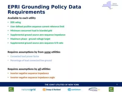
Tom Key and Devin Van Zandt EPRI June 26 2019 NYSERDA RampD NeutralGrounding for InverterConnected DER Research Project Abstract Challenge Grounding practices for rotating machine DER aimed to control ground fault overvoltage in utility distribution are not well defined for ungrounded inve ID: 765814

der grounding c62 inverter grounding der inverter c62 phase system transformer fault ground open systems feeder current sources effective

Share:

Link:

Embed:

Download Presentation from below link

Download Presentation The PPT/PDF document "Tom Key and Devin Van Zandt, EPRI" is the property of its rightful owner. Permission is granted to download and print the materials on this web site for personal, non-commercial use only, and to display it on your personal computer provided you do not modify the materials and that you retain all copyright notices contained in the materials. By downloading content from our website, you accept the terms of this agreement.


Presentation Transcript

Tom Key and Devin Van Zandt, EPRIJune 26, 2019 NYSERDA R&D Neutral-Grounding for Inverter-Connected DER

Research Project Abstract Challenge: Grounding practices for rotating machine DER aimed to control ground fault overvoltage in utility distribution are not well defined for ungrounded inverter-connected PV. Practices are evolving and requirements appear to be inconsistent across systems Developers point out that they are uncertain what requirements must be met. NYSERDA Study Objective: Define evaluation approach and methods to determine effective grounding (and/or supplemental grounding) configurations with inverter-based DER.

IEEE Guide for Neutral Grounding C62.92.1 – Introduction and definitions (vintage 1954) C62.92.2 – Synchronous generator systems C62.92.3 – Generator auxiliary systems C62.92.4 – Distribution systems (neutral grounding, 1972) C62.92.5 – Transmission and sub-transmission systems C62.92.6 – Systems supplied by current-regulated sources (2017)EPRI-NYDERDA analytical work to address practical applications of C62.92.6Screening of 3 or 4-wire DER connections w.r.t. primary transformer configurationSupplemental grounding transformers, sizing, effectiveness, other options Models used in short circuit protection tools (CAPE, ASPEN, CYME, Synergi) “ provides definitions and considerations related to system grounding where the dominant sources of system energization are current-regulated or power-regulated power conversion devices.”

Background/Motivation Traditional power system grounding (based on IEEE C62.92.1-5) addressed synchronous generators ( low-impedance voltage sources ) In 2017 IEEE C62.92.6 was added to address grounding of systems supplied by inverter DER ( current-regulated sources). With few exceptions, grid-connected three-phase inverter DERs are controlled to act as positive-sequence current sourcesThis behavior is fundamentally different than machines, indicating need to review and update effective (neutral) grounding practices. PV plant grounding requirements are not harmonized among different utilities and between jurisdictions of the same utility

DER System Grounding in the Unintentional Islanding Scenarios Inverter DER are expected to have insignificant effect on system grounding when the feeder breaker is closed The main concern is ground fault overvoltage (GFO) in case DER supports an unintentional island (feeder breaker open) with a ground fault GFO is the first order concern in this scenario

Conventional Notion of an “Effectively” Grounded Power System Effective grounding is defined as a Coefficient of Grounding ( CoG ) CoG  0.8 pu limits GFO to 0.8 x Vl-l or 0.8 x of Vl-g e ffective grounding is a system condition defined by voltages CoG  V L-G(fault) /VL-L(no fault)X0/X1  3, R0/X1  1 are an approximation (works for synchronous generators)Conventional situation:Relatively low impedance of rotating generator sources dominates systemLoads and other shunt impedances are relatively unimportant to fault and GFOV calculationsThus, a voltage source with a low X0/X1 will yield effective grounding when energizing any practical system  

DER Connection Screening Practice: Used in FERC-SGIP, NY SIR, CA Rule 21 and most states Aim to screen out DER connections prone to ground-fault overvoltage (GFO) and to limit allowed connection types based on concerns for ground fault and open-phase This table is commonly used (but may not be appropriate for inverter DER) Failing the screen typically leads to alternatives such as adding a grounding transformer

Project plans over then next 18 months TASK 1. Assess Current Utility Practice To Inform Objectives Determine Current Utility Practice (guided interviews) Clarify Grounding Objectives and Specific RequirementsTASK 2. Develop Relevant Scenarios and Models to be Analyzed (includes Laboratory and HIL Test, and Modeling Objectives) TASK 3. Coordinated and Concurrent Analysis, Simulation, and Testing TASK 4. Develop Guidelines for Inverter Effective Grounding TASK 5. Deliver Final Report, Outreach and Education (ITWG workshop later in 2019 and planning tutorial near the end of the project)

Q1 – What are your common transformer connections for 3-Phase DER?

Typical Grounding Practices for Synchronous Generator DER Feeder Feeder Grounding transformer on MV, GSU any configuration Grounding transformer on LV, GSU must be Yg-yg Yg -  GSU, no separate GT needed, neutral resistor (options) Feeder Feeder Grounded wye generator, GSU must be Yg-yg

Q2 –  When specifying a local ground source for DER, is your requirement the same or different for inverters and rotating machines of the same rating? 

Q3 – When do you require a DER to provide additional ground source (either by a grounding transformer or a grounded-wye/delta transformer)?

Tech Brief on DER Open Phase Reference: Distributed Energy Resources Field Experience: Open Phase ( 3002015949 ) Ceases to energize Transformer type   Open phase voltage Yg / Yg Yg /   / Yg 5-leg 3-leg 5-leg With GT and inverter capacitance Primary/ Secondary 1.2/1.18 pu ~1 pu ~1 pu Ferro-resonance Without GT, with inverter capacitance Primary/ Secondary Ferro-resonance ~1 pu ~1 pu Ferro-resonance Without GT and all capacitance Primary/ Secondary 0.6 pu 1 pu 1 pu < 0.5 pu

Q4 – Are you seeing more incidents and concerns for open phase because of DER Plants?  

Q5 – Are open phase commissioning tests conducted before DER installation? 

Questions/Comments?