/
VGZ-025 | 20120424.0Vogelzang International Corp.VG650ELG MOUNTAINPage VGZ-025 | 20120424.0Vogelzang International Corp.VG650ELG MOUNTAINPage

VGZ-025 | 20120424.0Vogelzang International Corp.VG650ELG MOUNTAINPage - PDF document

ellena-manuel
ellena-manuel . @ellena-manuel
Follow
415 views
Uploaded On 2015-09-10

VGZ-025 | 20120424.0Vogelzang International Corp.VG650ELG MOUNTAINPage - PPT Presentation

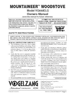
This stove meets US Test Standard MOUNTAINEERModel VG650ELG Owners Manualsave this manual for future reference Vogelzang International Corporation400 West 17th StreetHolland Michigan 49423wwwvo ID: 125535

This stove meets U.S. Test

Share:

Link:

Embed:

Download Presentation from below link

Download Pdf The PPT/PDF document "VGZ-025 | 20120424.0Vogelzang Internatio..." is the property of its rightful owner. Permission is granted to download and print the materials on this web site for personal, non-commercial use only, and to display it on your personal computer provided you do not modify the materials and that you retain all copyright notices contained in the materials. By downloading content from our website, you accept the terms of this agreement.


Presentation Transcript

VGZ-025 | 20120424.0Vogelzang International Corp.VG650ELG MOUNTAINPage 1 This stove meets U.S. Test Standard: MOUNTAINEERModel VG650ELG Owners Manual(save this manual for future reference) Vogelzang International Corporation400 West 17th StreetHolland, Michigan 49423www.vogelzang.comFax: 1-616-396-1971 READ ALL INSTRUCTIONS CAREFULLY NSTALLING OR OPERATING STOVE. FTOINSTRUCMAYRESULT NOTE: INSTALLATIONUALIFIEDHEATINGNSTALLER INSTALL TO STOVE INFORMATION OTICE: ISTOVENOTPROPERLYINSTALLED, BUILDING Page 2 | VG650ELG MOUNTAINvogelzang.comVGZ-025 | 20120424.0 SAFETY INSTRUCTIONS – Read All Instructions carefully. The installation of this stove must comply with your local building code rulings. Please observe the clearances to combustibles (see reference gures 7– 9). Do not place furniture or other objects within the clearance area.2.Verify that the stove is properly assembled and installed before ring the stove for the rst time. fter reading these instructions, if you have any doubt about your ability to complete your installation properly, you must obtain the services of a professional licensed installer familiar with all aspects of safe and correct installation. DO NOT TEMPORARYCOMPROduring installation. here must be NODEVIATIONALTERATIONfrom the very specic instructions spelled out in this instruction manual as it pertains to the installation of this woodstove. 3.DO NOT store wood, ammable liquids or other combustible materials too close to the unit. efer to certication label on back of unit and reference gures 7 – 9 in this manual.4.NOTINSTALLSTOVE, MANUFACTURED, – D Federal Standard: 24 CF5.NOTELEVATESTOVE(i.e. bricks under base, cement blocks) Stove pedestal base must set directly upon the solid-surface non-combustible floor as specied in this stove instruction manual. NOTSTOVE WAY! tove must be installed with pedestal base and ash drawer provided, attached as shown in the instructions. DO NOT OPERATE COVERPLACEssemble only with original parts as supplied and shown in this manual. DO NOT OPERATE A STOVE TAT IS MISSING ANY PARTS! f any parts are missing or defective, please notify the dealer or manufacturer immediately. eplace missing, broken or worn parts with factory original or equivalent parts only.6.CAUTION: DNOTALTERCOMBUSTIONCONTROLTO. ltering or tampering with air control beyond normal capacity will create unsafe 7. Always connect this stove to a chimney and vent to the outside. ever vent to another room or inside a building. DO NOT CONNECT TTO A CIMNEY FLUE SERVING ANOT8. NOT WBURNINGSTOVETOANALUMINUM TYPE B GAS. his is not safe. se code-approved lined masonry or a ppliance chimney. se a 6” diameter chimney or larger, that is high enough to give a good draft. (See specics in installation instructions).9.Be sure that your chimney is safely constructed and in good repair. Have the chimney inspected by the re department or a qualied inspector. Your insurance company should be able to recommend a qualied inspector. Chimney connector pipe must be in good condition. eplace if necessary before using stove.Creosote or soot may build up in the chimney connector and chimney and cause a house/building re. nspect the chimney connector and chimney twice monthly during the heating season and clean if necessary. (See Service Hints, page 14), turn the air controls to closed positions, leave the building and CALL TE FIRE DEPARTMENT IMMEDIATELY! Have a clearly understood plan on how to handle a chimney re by contacting your local re authority for information on proper procedures in the event of a chimney re. fter the re is out, the chimney must be cleaned and inspected for any stress or cracks before starting another re. Check the condition of any combustibles surrounding the chimney. To prevent injury, do not allow anyone to use this stove who is unfamiliar with the correct operation of the stove.13.Do not allow ashes to accumulate above top of ash drawer.in a steel container with a tight tting lid and moved outdoors immediately. he closed container of ashes should be placed on a noncombustible oor or on the ground, well away from all combustible materials, pending nal disposal. disposed of by burial in soil or otherwise locally dispersed, they should be retained in the closed container until all cinders have completely cooled. ther waste shall not be placed in this container. 15. The special paints used on your stove may give off some smoke and an odor while they are curing during the rst 12 to 15 res. tional smoke and odor may be emitted from the light oils used in construction of the re box. his should disappear after a short period of time and not occur again. Persons with lung conditions or owners of susceptible domestic pets (such as birds) should take prudent precautions. pen windows and doors as needed to clear smoke and/or odor. Paint discoloration will occur if the stove is over red.his stove has a painted surface which is durable but it will not stand rough handling or abuse. When installing your stove, use care in handling. VGZ-025 | 20120424.0Vogelzang International Corp.VG650ELG MOUNTAINPage 3 DO NOT ELEVATE Tthe bottom of the rebox. his stove has not been tested with the use of grates, andirons or other means of elevating the re and must not be used.STOVEUENTLYas soot, creosote and ash may accumulate. Clean exterior with soap and warm water when stove is not hot. Do not use any acids or scouring soap, as these solvents wear and dull the nish. Do not operate stove while under the inuence of drugs or alcohol LERTTOSURFACETEMPERATURESwhile stove is in operation – especially young children. Keep away from a hot stove to avoid burns or clothing ignition. LEAVEVISED WHENEYAREINSAMEROOMSTOVEroom as the stove during operation, provide a sturdy barrier to keep them at a safe distance from the stove. Keep stove area clear and free from all combustible materials, gasoline, engine oil, naphtha and other ammable vapors and liquids.AYS WPROCLOT, re retardant hearth gloves and eye protection, to prevent burns.OPERATESTOVE WH PLACE except when re-fueling. Such actions can result in very dangerous operating conditions.NOTOVERSTOVEver ring will occur if combustion air is uncontrolled as when opersated without ash cleanout cover or ash drawer or if feed door is left open during operation. Such actions can result in very dangerous operating conditions. While in operation, keep the feed door closed and secured at all times except while tending the reNOTSMOT WH. Do not build res against glass and do not load fuel to a when opening the door.NEVER LEAVE TE STOVE UNATTENDED with door open. lways close the door after ignition. DO NOT CONNECT TO OR USE IN CON ANY AIR DISTRIBUTION DUCT UNLESS SPECIFICALLY APPROVED FOR SUCINSTALLATIONS.A WBURNINGSTOVEINSTALLEDAYSTAIR as it may block egress in the event of a re.NOTINSTALLROOMNOTINSTALLALCOVEFIREPLACESAFETY INSTRUCTIONS continued… Install at least one smoke detector on each oor of your home. Detectors should be located away from the heating appliance to avoid false alarms. Detectors should be located close to sleeping areas. Follow the smoke detector manufacturer’s placement and installation instructions. Maintain smoke detector per manufacturer’s instructions. ONOXIDE buildup of fumes is toxic and can be fatal. Carbon Monoxide is a colorless, odorless gas produced during combustion of wood, coal, oil, gas and by other fuel burning appliances. t is important to have a proper draft and adequate replacement air ventilation so fumes are drawn out the chimney. nstalled as instructed this stove is designed to be as safe as possible yet it is detector. Follow the manufacturer’s recommendations for proper installation and use. t is recommended to be placed at table-top level (not near the ceiling) to avoid false alarms. ealize that devices other than a stove (i.e. motor exhaust) can trigger C alarms. If alarm sounds: • Recognizeaches, nausea & drowsiness). • increaseventilationwindows • Makestove • Checkstoveforair�ow • Checkchimneyforleaks,blockage or down-draft conditions. • Checkdeviceforfalsealarm.34. The walls of the re box may become slightly distorted after a period of use. slight distortion will not affect 34 operation of the stove.Keep power cords, electrical appliances and/or assemblies outside of the clearance area shown in this manual for combustible materials. Consult your municipal building department or re ofcials about restrictions, permits and installation requirements for your area.37.For further information on using your stove safely, a copy of the ational Fire Protection ) publication, “sing Coal and Wood Stoves Safely” o. HS-10-1978. Write , Batterymarch Park, Quincy, MNOTE: A PROFESSIONAL, EATCONTRACTORCONSULTEDYOUAVEINSTALLATIONBURNING Page 4 | VG650ELG MOUNTAINvogelzang.comVGZ-025 | 20120424.0 NSTRUCTIONSNOTICE: Vogelzang International Corp. grants no warranty, stated or implied, for the installation or maintenance of your wood stove and assumes no responsibility of any incidental or consequential damages. TOOLS ATERIALSNSTALLATION • Pencil6 foot Folding Rule or Tape MeasureDrill: Hand or Electric1/8” dia. Drill Bit (for sheet metal screws)Screwdrivers (blade and Phillips type)14mm Nut Driver or Ratchet with 14mm SocketSafety GlassesGloves MATERIALS (NOTE: The following items are NOTincluded with your stove)Flooring Protection: 48” x 48” as speci�ed (see page 6)Chimney Connector Pipe: 6” dia. minimum 24 MSG black or 26 MSG blue steel stove pipe or elbow(s) as required.1/2” Sheet Metal ScrewsChimney: Existing 6” code-approved, lined masonry chimney or 6” inside dia. Listed UL 103 HT manufactured chimney.Furnace Cement (manufacturer recommends Rutland Code 78 or equivalent)CAUTION: STOVEEAVY. MYOUAVEUATEPROPERLIFTINGTECNIUES WHENEVERMOVINGSTOVE1.Uncrate the stove and remove all cardboard and styrofoam packing materials and protective poly bag. Remove rear deector (#2), pedestal ton. (Save cardboard for further assembly.)Remove parts from inside stove. Parts include: damper (#5), damper collar (#4), blower assembly (#3), ash drawer (#13), pedestal front (#17), pedestal sides (#15), pedestal drawer support (#16), and hardware pack (#19) located inside 5.Insert the pedestal drawer support (#16) into the pedestal assembly. Secure with two (2) sheet metal screws from the back of the assembly. 3.Using machine screws, lock washers and hex nuts, attach the pedestal sides (#15) to the ped4.Attach the front panel (#17) of the pedestal base over the sides, gure 2. Attach the front panel to the side panels with machine screws, lockwashers and hex nuts (three each side).Figure 1 Figure 2 Attach Front Panel to Side Panels. Figure 3 Insert the Drawer Support inside the Attach the top plate to the pedestal assembly, gure 4, with machine screws, lockwashers and hex nuts.Figure 4 Attach the Top Plate to the pedestal base assembly. continued on next page VGZ-025 | 20120424.0Vogelzang International Corp.VG650ELG MOUNTAINPage 5 CAUTION: STOVEBODYEAVY. MYOUAVEUATETOSTOVEBODYPEDESTALPROP. tip the stove box assembly (#1) onto it’s back. Prop up the bottom edge with additional packing material or wood pieces.Tip the pedestal base assembly back and align in the bottom of the stove box. Secure with hex nuts and tighten. NOTE: By design the pedestal 9.Carefully lift the stove to the upright posiInsert the ash drawer (#13) into the pedestal 11. After properly locating flooring protector stove clearances, place stove in position on oor protector.ners of the stove using four screws provided. Attach blower assembly (#3) to back of rear deector. NOTE: Make sure ceramic gasket blower assembly and is properly aligned so it doesn’t block the fan, Figure 5.14.Install damper (#5) into damper collar (#4) [see damper installation below] and secure to top surface of stove using machine screws. Figure 5 Align Ceramic Gasket with blower fan opening before mounting.NSTRUCTIONScontinuedNSTAATION Fig. 6 – Cast Iron Damper1. Position collar onto hole in stove top and align Secure the collar to stove with bolts and nuts Install damper into collar as shown in lower 4.Insert damper handle through collar into damper and out the opposite side of collar. BoltNuDampeCollarTop Page 6 | VG650ELG MOUNTAINvogelzang.comVGZ-025 | 20120424.0 LOCATINTOThe stove must be placed on solid concrete, solid masonry, or when installed on a combustible oor, on a listed UL 1618 Type 2 oor protector, such as Hy-C or Imperial Model UL4848BK or equivalent with 1.0 R-factor. (NOTE: to calculate R-value of alternative materials see page 20). The base must extend at least 16 beyond the front of the access door, 8 to the sides, 8 behind and must extend under and 2 inches beyond either side of the stove pipe if it is elbowed towards a wall. (See gures 7 & 9 and consult local building codes CAUTION: (FOTCOMBUSTIBLEMATERIALNOTCOVERPROTECTOR. THMATERIALSCOMBUSTIBLE, . 7– 9.The stove must have its own ue. NOTTOSERVINGOT3.After observing the clearances to combusprotector accordingly (figure 7) and carefully place the stove in your selected location. Install connector pipe, elbows, and thimble as required, utilizing either a recently cleaned and inspected 6” masonry chimney or a 6” i.d. UL 103 HT listed chimney.Fig. 7 – Minimum Clearance Dimensions from Combustible Surfaces FLOORPROTECTOR DASHED LINES SHOW HORIZONTAL CHIMNEY CONNECTORAND ADDITIONAL FLOOR PROTECTOR REQUIRED BENEATH AND EXTENDING 2” BEYOUND EACH SIDECOMBUSTIBLE CONSTRUCTION IN ACCORDANCE WITH NFPA 211 BACKWALL SIDEWALL 8"min.17"48"16"min.8"min.28" 25"min. 26"minMINIMUM CLEARANCES TOP VIEW 44" VolgelzangUse 48Standard SizeFloor Protector mum standard gauge) black or 26 MSG blue steel stove pipe. DO NOT use galvanized stove pipe. Secure pipe/elbow sections with three sheet metal screws at each joint to make the piping rigid. Screws may be no more than a OTSTOVETOBUTION5.Recheck clearances from the stove, connector stove pipe, and corner clearances using the illustrations in figures 7–9 and your local building codes or re protection NOTE: A WFACED WDRY, STONECOMBUSSURFACESTALL THIS STOVE I A MOBILE UFACTURET OR (HUD Federal Standard: 24 CFR Ch.7.The clearances provided are minimum dimensions determined by US Test Standard UL 1488-1996, tested and applied by Intertek Testing Services, the manufacturer’s testing laboratory. Installation of this stove must comply with the latest edition of NFPA 211 for reduced clearances and/or your local building code rulings. Use whichever minimum dimensions are LARGEST.8.This stove meets U.S. Test Standard: continued on next page VGZ-025 | 20120424.0Vogelzang International Corp.VG650ELG MOUNTAINPage 7 LOCATINTOcontinued…Fig. 9a – Front Viewfrom Combustible SurfacesFig. 9b – Side Viewfrom Combustible SurfacesCAUTION: OTCOMBUSTIBLEMATERIALSAYFROMSTOVENOTE: B WOODSTOVETO 18-1/2"18-1/2"CORNER CLEARANCES Fig. 8 – Top Viewfrom Combustible Surfaces Page 8 | VG650ELG MOUNTAINvogelzang.comVGZ-025 | 20120424.0 CONNECTORNSTAATIONThe crimped end of the stovepipe ts inside the stove ue collar. Install additional pipe and elbow with the crimped end towards the stove. This will allow any condensation in the ue to run back into the rebox. Secure pipe/elbow sections with three sheet metal screws at each joint to make the piping rigid. Screws may be NOTE: The rst section of connector pipe must be single-walled to properly attach to the ue collar.2.Horizontal pipe runs must slope upwards towards the chimney at least 1/4” per foot of You must have at least 18 inches of clearance between any horizontal piping and the ceilThe pipe cannot extend into the chimney ue 5.Secure pipe/elbow sections with three (3) sheet metal screws at each joint to make the piping rigid. Screws may be no more than 3/76mm It is recommended that no more than two (2) 90° bends be used in the stovepipe installation. The use of more than two 90° bends may decrease the amount of draw and possibly cause smoke spillage. Where possible, use only corrugated (nonadjustable) elbows. These provide a better seal.attic or roof space, closet, or any concealed space, or oor, ceiling, wall or combustible construction. (See Chimney Connector Systems & Clearances, page 12). A UL 103 HT listed chimney system be used from the rst penetration of ceiling or wall to the chimney cap. Any ceiling or wall penetrations must conform to NFPA 211. Use only one manufacturer’s chimney components – do not mix manufacturers. ARNING: DO NOT WNECTOR - HRESULT. Fig. 10 – Stovepipe/Flue ConnectionsRONGRONG NOTE: STOVENOT INC, VYOUR, BUILDING. UROUND6” ia., 24 MSG (minimum standard gaugeBLACSTOVEPIPE. DO NOT USEGALVANIEDSTOVE VGZ-025 | 20120424.0Vogelzang International Corp.VG650ELG MOUNTAINPage 9 CHIMNEYFLUE 5/8" TILECHIMNEYLINER MASONRYCHIMNEY THIMBLE COLLAR 6 ROUND24 ga. BLACKSTOVEPIPE 8 MIN.LINERBELOWENTRYHOLE ASONRYChimney must be a code-approved, masonry chimney with ue liner. Before using an existing masonry chimney, clean the chimney, inspect the flue liner and make any repairs needed to be sure it is safe to use. Make repairs before attaching the stove. The connector stove pipe and ttings you will need to connect directly to a masonry chimney are shown in The stove must be connected to either a masonry or manufactured metal chimney built and tested to the specications listed on the previous Chimneys perform two functions:1). As a means of exhausting smoke and ue gases which are the result of fuel combustion. 2). The chimney provides “draft” which allows oxygen to be continuously introduced into the appliance, so that proper combustion is possible. This stove relies on natural draft to operate.NOTICE: Always provide a source of fresh air into the room where the stove is located. Failure burning appliances and the possible development Your stove itself does not create draft. Draft is provided by the chimney. To achieve proper draft your chimney must meet the three minimum height requirements detailed in gures 12–14. A minimum of 0.05 w.c. (measured in water column) is required for proper drafting to prevent back pufng, smoke spillage, and to maximize performance. (Gauges to measure draft are readily available at stove stores Factors such as wind, barometric pressure, trees, terrain and chimney temperature can have an adverse effect on the draft. The manufacturer cannot be held responsible for external factors Should you have a problem with inadequate cooling contractor for assistance in solving the IMPORTANT Installation Points1.Size chimney ue to stove collar. This stove Never connect this unit to a chimney serv3.The chimney must meet all minimum Never use a chimney to ventilate a cellar 5.Contact your local building authority for approved methods of installation and any Fig. 12 - Chimney Construction Through Attic Space Fig. 11 - Masonry Chimney ConnectionIf the connector stove pipe must go through a combustible wall before entering the masonry chimney, consult a qualied mason or chimney dealer. The installation must conform to local building and re codes and latest edition of NFPA chimney, close it tightly. Page 10 | VG650ELG MOUNTAINvogelzang.comVGZ-025 | 20120424.0 Fig. 13 - Chimney Construction Through Roof Fig. 14 - Chimney Connection to Firebox Through Masonry continued …ANUFACTUREDTONECTORINSTRUCTIONSINSTALLATIONUse only 6” diameter listed chimney UL 103 HT. Chimney made to this listing is High Temperature rated to 2100 degrees Fahrenheit. Use chimney from only one manufacturer. Never mix brands. Carefully follow the chimney manufacturer’s stated requirements and clearances. Use the chimney manufacturer’s attic guards, roof supports, ashing and re stops when passing through a combustible wall. Do not use makeshift ARNING: DOTWhen using a pre-existing chimney, have it’s condition and installation inspected before using. Make sure that the chimney meets all of the UL rating requirements listed above. Be aware that not all manufactured chimney is of the UL 103 HT type.NOTE: It is recommended that you contact a licensed heating and cooling contractor (consult your local yellow pages) for chimney installation.Manufactured chimney with the proper required UL listing is available from most home centers, hardware stores, and HVAC supply stores.If you have access to the internet, you may wish to view chimney manufacturers’ information on-line. See, www.duravent.com, www.selkirkinc.com, or www.mtlfab.com.TOIREPLACEIn some instances, people desire to convert an existing replace for stove use. Usually, safe connection to an existing masonry chimney requires more work than using a prefabricated chimney. The existing replace must be closed and sealed at the damper with high-temperature caulk, ceramic wool, or furnace cement. Prior to installation, clean and inspect the existing ue and smoke shelf. Installation should be designed so inspection. Before conversion, make sure the existing chimney is structurally sound, the chimney incorporates a ue liner and make sure it is in good condition. (A ue liner consists of clay tile that protects the brickwork of a chimney. If a chimney does not have a liner, or it is damaged, have it relined by a professional. OT continued on next page VGZ-025 | 20120424.0Vogelzang International Corp.VG650ELG MOUNTAINPage 11 continued … a chimney that is unlined or damaged!have any question regarding the condition of the chimney, consult a qualied licensed contractor, qualied engineer, competent mason, certied Chimney Sweep, or a knowledgeable inspector. Consult your insurance company if you cannot nd a qualied expert.CAUTION: NOTFIREPLACESUITABLETOACCOMMODATETOSTOVE. CHK WUALIFIEDEXPERTMany prefabricated replaces are of the “zero-clearance replace” category. These consist of multi layered metal construction. They are designed with and sides so they can be safely installed in direct contact with combustible oors and walls. Although many prefabricated replaces carry endorsements from nationally recognized organizations for use as replaces, they have not been tested for connection to wood stove heaters. Connecting a stove to such a device will void the manufacturer’s warranty.Venting a stove directly into a replace does not meet code and should not be attempted. The stove warranty will be void with such an installation. Do not create a hazard in your home by connecting in this manner.IREPLACENSTALLATION FIG. 15 - Fireplace Conversionshould insure proper clearance for a 6 stovepipe.2.Install a re clay (5/8 minimum thickness) thimble. Make sure the thimble is ush with the inner surface of the chimney liner and does not protrude into the 3.Secure the thimble with refractory mortar. The thimble should be surrounded by 12 of solid unit masonry brickwork or 24 of stone.Install the stovepipe into the thimble as far as possible without extending past the ue lining (see 5.A small airspace (about 1/2) should remain between the stovepipe and thimble to allow for expansion of the pipe. Seal this airspace with high-temperature caulking or ceramic wool.using high-temp caulking, ceramic wool, or furnace cement. Also check to see if the chimney has a cleanout. If it does, make sure it is closed and sealed as well. A leaky cleanout will greatly reduce draft efciency.If you have any questions regarding venting your stove, contact the manufacturer or contact the National Fire Protection Association (NFPA) and request a copy of the latest editions of NFPA Standard 211 and NFPA Standard 908. Their address is: Battery March Park, Quincy, MA 02269. Directly connecting the stovepipe into the existing masonry chimney (gure 15 “Type A” Fireplace Conversion) of the replace is the only approved method of installation. This is a complicated and involved done by a qualied installer.masonry and tile liner with minimal damage to the liner. At least 8” of liner must remain below the entry position. When locating the stove and stoveobserved from combustible surfaces including mantels, combustible trimwork, ceilings and walls. Positioning the center of the stove pipe entry into the chimney 24 below the ceiling Continued on next page Page 12 | VG650ELG MOUNTAINvogelzang.comVGZ-025 | 20120424.0 bustible wall with a minimum of 12/305mm brick separation from clay liner to combustibles. The reclay liner shall run from outer surface of brick wall to, but not beyond, the inner surface of chimney ue liner and shall be rmly cemented in Insulated SleeveSolid-insulated, listed factory-built chimney length of the same inside diameter as the chimney connector and having 1/25.4cm or more of insulation with a minimum 9/229mm air space between the outer wall of the chimney length and combustibles.Ventilated ThimbleSheet steel chimney connector, minimum 24 gauge in thickness, with a ventilated thimble, minimum 24 gauge in thickness, having two 1/25.4mm air channels, separated from combustibles by a minimum of 6/152mm of glass fiber insulation. Opening shall be covered, and thimble supported with a sheet steel support, minimum 24 gauge in D.Chimney Section Pass-throughSolid insulated, listed factory-built chimney length with an inside diameter 2/51mm larger than the chimney connector and having 1/25.4mm or more of insulation, serving as a pass-through for a single wall sheet steel chimney connector of minimum 24 gauge thickness, with a minimum 2/51mm air space between the outer wall of chimney section and combustibles. Minimum length of chimney section shall be 12/305mm chimney section spaced 1/25.4mm away from connector using sheet steel support plates on both ends of chimney section. Opening shall be covered, and chimney section supported on both sides with sheet steel support securely fastened to wall surfaces of minimum 24 gauge thickness. Fasteners used to secure chimney section shall not penetrate chimney ue liner.ONNECTOR VGZ-025 | 20120424.0Vogelzang International Corp.VG650ELG MOUNTAINPage 13 ERATINNSTRUCTIONSThis stove is designed to burn OOD FUEL ONLY!Hardwood, 16” to 18” should be air dried maximum burning efciency. Logs greater than 6in diameter should be split. Wood should be stored in a dry, well ventilated area. The humidity content of usable rewood should be no more than Attempts to use wet or unseasoned wood will • rapid creosote buildup resulting in chimney �re• incomplete combustion• low heat yield• blackened windowsNOTICE: U WMATERIALSONLY. OTBURNGARBAGE. DOTOAL THSTOVENOTTOACCOMMODATEW NECESSARYTOPROPERLYBURNCOALCOALPRODUCTS. DNOTELEVATEGRATESANDIRONS. BDIRECTLYBOTTOMFIREBOXOpen draft damper fully to provide maximum Open the feed door and place several wads of Light the paper and kindling, close the door and secure tightly.Add fuel after re is burning briskly. Use care not to smother the kindling re when adding wood. Close the door and secure tightly.7.Adjust the draft damper control. The more closed the slower the re will burn. The more open, the faster and hotter the re will burn.Do not over re the stove.Add small amounts of fuel each hour or so instead of piling large quantities of fuel at one time. This will insure a more complete combustion CAUTION: woo oTOR, UNDERNEATH STOVEPIPEANY WFROMCOMBUSTIBLESURFACESSTOVE oay a . OVERCONNECTORPERATINGRECAUTIONS OVERSTOVEBUILDEXCESSIVELYOTBUILDINGMAYRESULT. YOVERSTOVESTOVEPIPETO BUILDEXTREMELYSTOVEDAMAGETOSTOVEAGEMAYRESULT W, NOTBUILDTOOTO OT WHOPERATION. , CLOT, AY. ONTACTMAYCAUSEBURNS. DNOTTOUCH STOVEAFTERFIRINGUNTIL ROVIDEINTOROOMPROPCOMBUSTION6. STOVEPIPEEVERYDAYS. EPLACEIMMEDIATELYSTOVEPIPERUSTINGINTOROOM ARNING: E, , , KEROSENE, ARCOAL, TOSTART “” a ov a, ESPECIALLYGASOLINE, OUTEATER — WHSTORAGE Page 14 | VG650ELG MOUNTAINvogelzang.comVGZ-025 | 20120424.0 process and less buildup of tars, soot, or creosote will occur in the chimney.Always open draft damper before opening the feed door.2.When adding fuel be careful not to smother the re. Do not build res against glass on models with glass door.Close the feed door and secure tightly.5.Empty ashes regularly. Do not allow ashes to pile up (see Safety Instructions #14 on 6.Properly dispose of hot ashes (see Safety Do not over re the stove.CAUTION: DO NOT OVER FIRE APPLIANCE. OVERCONNECTORSSTOVE. CDAMPERDIATELYTOSUPPLYTO. TH WCAUTION: SBURNINGMAYCAUSECREOSOTEBUILDUP. ISOTEBUILDUPOVERMAYCAUSE. CHBURNEXTREMELYOTMAYSURROUNDINGMATERIALS. IDEPARTMENTIMMEDIATELY ERATINcontinued … CREOSOTE – FORMATIONEMOVALCAUTION: RIS OF FIRE EN WOODISBURNEDLY, PRODUCESTAROTVAPORS, WHTOSOTE. THCREOSOTEVAPORSRELATIVELYW-BURNING. ARESULT, CREOSOTEACCUMULATES. CREOSOTEEXTREMELYOTCONNECTOROULDBEINSPECTEDATLEASTONCEEVERYEATINGTOCREOSOTEBUILDUPCREOSOTEACCUMULATEDREMOVEDTOFailure to remove creosote may result in ignition and may cause a house/building re. Creosote may be removed using a chimney brush or other commonly available materials from your local hardware retailer.Chimney res burn very hot. If the unit or chimney connector should glow red, reduce the re by closing the inlet air control and immediately CAUTION: A MAYCAUSE W WHASSUMEDTODISTANCEFROM. I, HAVEYOURUALIFIEDXPERTAGAINing a large quantity of coarse salt, baking soda, or REOSOTECreosote will inevitably form in your chimney and connector pipe. Following these steps will help reduce the rate of build up. BURN ONLY SEASONED dried for at least one year. (humidity by Burn hardwood rather than softwood. Hardwood is denser or heavier wood and burns hotter. VGZ-025 | 20120424.0Vogelzang International Corp.VG650ELG MOUNTAINPage 15 continued … 4. Do not attempt to burn (or mix in) green or wet wood. The use of green or wet wood will cause a rapid build up of creosote. Wood that hisses, sizzles and blackens without igniting in ve minutes must be considered too wet to burn.5. Do not attempt to extend the burn time by using wet wood. Not only does burning wet wood rapidly build up creosote, but it reduces the heat 6. Burn the stove with the air inlet control wide open for 10-25 minutes every time fresh wood is loaded into the stove. Do not load more than ¼ to ½ of the fuel capacity at one time. Loading too much wood at once will cause excessive smoke which contains creosote. Mature res or coals produce very little creosote-producing smoke.Burn with the control open for several minutes at numerous intervals throughout the day, being careful not to over re the unit. Following this process will help to warm the chimney and reduce the amount of creosote forming condensation within the chimney.8. ing, and operating the stove. Check daily for creosote build up until experience shows how aware that the hotter the re, the less creosote essary in mild weather even though monthly ARNING: I: CONTROLDEPARTMENTThe chimney is critical to the proper operation of the stove. It is the chimney that creates draft; THE STOVE DOES NOT AND CANNOT CREATE DRAFT. The chimney provides two vital functions for proper stove operation. First, it is the passage to exhaust smoke and hot gases created in the combustion process. Secondly, it supplies to sustain combustion. Draft is the natural movement of air or gases through a chimney. Chimney draft comes from the natural tendency for hot (less dense) air to rise. As the hot air rises within the chimney it creates a lower pressure at the bottom of the chimney to which the stove is connected. The higher pressure air outside the stove then rushes into the stove where the lower air pressure level exists, thus bringing oxygen to the re. This constant ow of air is referred to as the draft. Many factors or combination of factors can act together to build or impede the draft. Without the correct amount of draft, the stove will not operate properly. If there is excessive draft, an unsafe condition will arise with too much air being drawn into the stove and creating an excessively hot re. This could cause over ring which runs the risk of igniting structural elements around the stove and chimney.The most common experience is that of insufthe re will be starved for oxygen, improper or incomplete combustion occurs resulting in smoke spillage into the area around the stove. A re that is starved for oxygen will not burn well. Such a re will produce excessive smoke that will cool and condense in the chimney creating creosote. Excessive amounts of creosote buildup can ignite causing a chimney re with the possibility of strucCorrect any draft related issues before using the stove. The following are some possible causes factors may play a role in a draft issue and certain factors may change over time as conditions vary.Atmospheric Pressure and Air SupplyAtmospheric pressure that affects the draft may occur from outside the structure, inside the structure, or both. High pressure weather (clear and cold) usually produces a better chimney draft than low pressure (overcast and damp) conditions. Negative pressure can be created inside a home by appliances that expel air from within such as bathroom vents, range hoods, clothes dryers, and forced air furnaces. Do not allow such appliances to overcome the natural draft. Note that newer homes tend to be built more tightly allowing less make up air to seep freely in. Negative pressure may be overcome by opening a nearby door or window. In extreme conditions of negative draft, the airow in the chimney will reverse direction. This is known as “down drafting.” Page 16 | VG650ELG MOUNTAINvogelzang.comVGZ-025 | 20120424.0 continued Environmental FactorsWind or air deecting off external objects such as the roof, neighboring structures, trees, or hills. These can cause a pressure change in the air surrounding the chimney. Chimney TemperatureThe temperature of the chimney is an important factor in how well it drafts. Warm chimneys draft better than cold chimneys. This is based air sinks. Hot gases going up a cold chimney will cool rapidly. Warm the chimney by allowing a hot re to burn for the rst fteen to thirty minutes after starting the re. Be careful not to over re the stove. If any part of the stove or chimney starts to glow, you are over ring the stove. Masonry chimneys will take longer to warm than manufactured chimneys on account of their greater structural mass. Chimneys that have a ue diameter larger than the stove outlet take more heat to warm, thus resulting in a faster cooling of the hot gases needed to build or maintain draft. Chimney Installation and MaintenanceConfirm that four chimney height requirements listed in the Chimney Connection section of the manual have been met. The physics that link chimney height with of the stove. Failure to meet each of these minimum requirements will have an adverse affect on draft. Avoid long horizontal runs or multiple elbows. Use stove cement to seal joints in the connector pipe section. Regularly clean the chimney, connector pipe, rain cap, and spark arrestor screen. Creosote build up can reduce the chimney draw and possibly create a chimney re.Temporarily out of OperationAfter the re has burned out, open the air control to its fully open position. This will allow warm room air to enter the chimney and keep it as warm as possible until the stove is used again. For assistance involving chimney draft issues, contact a knowledgeable licensed heating and cooling contractor in your area. For questions regarding manufactured chimney, contact the manufacturer of the chimney. NOTE: A TO 0.06 W.. WATERPROPERBURNINGSTOVEAUTION: DNOTOPERATE WCRACBROprevent accumulations of ash. Acidic ash buildup can eventually etch and weaken glass. Creosote accumulations should burn off during hot res. The following usage and safety tips should be observed:1.Inspect the glass regularly for cracks and breaks. If you detect a crack or break, extinguish the re immediately and contact the manufacturer for a replacement before re-ring the stove.glass. When closing doors, make sure that logs Do not build res against (or that might fall against) the glass.4.Do not clean the glass with materials that Scratches on the glass can develop into cracks Never attempt to clean the glass while the unit is hot; allow to dry thoroughly before reuse. If deposits are not very heavy, normal glass cleaners are adequate using a soft, non-abrasive Never put substances which can ignite explosively in the unit. Even small explosions in conned areas can blow out the glass.EPLACEMENTARNING: REPLACE ONLY WH TEMPERATUREPROPER. DNOTMATERIALS WONTACTSTOVEMANUFACTURERREPLACEMENTGasket and Glass cleaning products are available at local retail home centers. Manufacturers of cleaning products include, A.W. Perkins Co. (www.awperkins.com) or Rutland Products (www.Glass Replacement Procedure:1.Ensure appliance is not in operation and is Remove screw and glass clips. (See parts list VGZ-025 | 20120424.0Vogelzang International Corp.VG650ELG MOUNTAINPage 17 continued VGOUNTAINEERSTO Remove glass from door frame.4.If glass is broken, carefully remove and discard each broken piece to avoid cuts. Discard window gasket. Replace window and gasket with original factory replacement parts.Replace new gasket starting at the bottom of glass working along edges, being sure to center gasket channel on glass.Trim to length and butt ends together.7.Perform replacement procedure in reverse order after replacing glass and gasket.When replacing glass into door, be sure not to overtighten screws and clips.EPLACEMENTAUTION: DNOTOPERATESTOVEATMATERIAL. OOPERATINGMAYRESULT. After extensive use, the gasket material which provides glass and door seal may lose it’s resiliency and will need to be replaced. Inspect glass and door gaskets periodically to ensure proper seal; if gaskets become frayed or worn, replace immediately.1.Ensure appliance is not in operation and is Remove old door gasket and clean channel.Using an approved, high temperature gasket Starting at hinge side of door, work gasket into channel around door unit, end butt and trim to Close door and allow three to four hours for The optional blower is maintenance free other than cleaning. Lightly vacuum motor and air inlet to keep free of dust and dirt. NOTICE: AREPLACE WAVEUIVALENTTEMPERATURERATING NOTICE: DOTW ERCORDTOTOUCH OTSURFACES. POERCORDATLEASTov oSURFACES AUTION: MOVINGPARTSCAUSEURY. DNOTOPERATE WCOVERREMOVED DANGER: SH. DINSTALLATION WHSERVICINGASSEMBLY Page 18 | VG650ELG MOUNTAINvogelzang.comVGZ-025 | 20120424.0 PARTSVGOUNTAINEERSTO Part No.ty. Part No.ty. Pedestal Front Pedestal Base Hardware Pack (not shown) Fire Brick Pack (only one brick shown) A Size: 9”x4.5”x1.25” Half Size: 4.5”x4.5”x1.25” Blower Housing (only) Blower/Motor (not shown) Power Cord (not shown) Cord Strain elief (not shown) Speed Control (not shown) Ceramic Fiber Gasket (not shown) etainer Screws (shown on pg 15) ssembly (less handle) Stove Body Blower ssembly F-6 Cover, Stove Door Frame ssembly Gasket, 3/8” dia. Fiberglass Glass Door Glass, Hi-emp Ceramic etainer Brackets (shown on pg 15) Ash Drawer Pedestal Pedestal Side Pedestal Drawer Slide When ordering missing or replacement parts, always give the of the stove,Part NumberPart Description. Use the illustrations and part lists provided to identify parts. VGZ-025 | 20120424.0Vogelzang International Corp.VG650ELG MOUNTAINPage 19 PARTSVGOUNTAINEERSTO Part No.ty. Door Frame 3/8” dia. Fiberglass Glass Gasket emp Ceramic Glass Retainer Screws ssembly (less handle) lass replacement instructions for model VGARNING: REPLACE ONLY WH TEMPERATUREPROPER. DNOTMATERIALS WONTACTSTOVEMANUFACTURERREPLACEMENTCAUTION: REMOVINGBRO, WGLOVES. AYBROSAFELYBe sure stove has cooled before beginning.Using a screwdriver, remove all screws (#27) 3.Remove glass (#10). Replace with original manufacture’s high-temperature ceramic glass only.When replacing broken glass, remove gasket (#9) from broken glass and discard, remove all glass pieces. Place new gasket material and trim to butt ends together.Reinstall glass, gasket and retainers. WARNINGReplace only with original manufacturer WARNING: Do not slam door or strike glass. WARNING: Do not use abrasive cleaners on glass surface. Abrasives can damage the glass CAUTION: Do not build re directly against CAUTION: Do not operate stove with cracked or broken glass.NOTICE: Periodically clean ash from glass surfaces. Prolonged contact with acidic ash can etch glass and weaken it. When ordering missing or replacement parts, always give the of the stove, Part Part Description. Use the illustrations and part lists provided to identify parts. Page 20 | VG650ELG MOUNTAINvogelzang.comVGZ-025 | 20120424.0 PROTECTORMATERIAATIONSThis stove has been tested for and must be installed on a oor protector with the proper Thermal Resistance or R-value as stated in the installation instructions on page 6, “Locating Stove” step 1, of this manual. If the oor protector materials listed in the instructions are not available, materials with an equivalent R-value may be substituted. Alternate materials may be rated with C-factor (Thermal Conductance) or k-factor (Thermal Conductivity) ratings which must be converted to R-value to determine if the alternate material meets the tested requirements. The following instructions provide the proper information and formulas for conversion to R-value.To determine if alternate materials are acceptable follow this sequence.Convert material specications to R-value:a. R-value given — no conversion necessaryb. k-factor is given with a required thickness (T) in inches: R = 1/k x Tc. C-factor is given: R = 1/CDetermine the R-value of proposed alternate oor protector:a. Use formulas in step 1 above to calculate R-value of proposed material(s). b. For multiple layers, add R-values of each layer to determine overall R-value.If the overall R-value of the oor protector system is equal to or greater than the oor protector specications given, the alternate is acceptable.Thermal conductivity (k) = The specs of oor protector material should be 3/4-inch thick material with a k-factor of 0.84.The proposed alternative material is 4” brick with a C-factor of 1.25 over 1/8-inch mineral board with a k-factor of 0.29.Convert specs to R-value. R = 1/k x T = 1/0.84 x 0.75 = 0.893 System must have a R-value of 0.893 = RspecsStep 2: Calculate R-value of individual components 4” Brick with C-factor = 1.25. R = 1/C = 1/1.25 = 0.80 = Rbrick 1/8-inch (0.125”) mineral board with k-factor = 0.29. R = 1/0.29 x 0.125 = 0.431 = Rmin.brd.Step 3: Add R-values of components to get total R-value of system Rsystem = 1.231 is larger than Rspecs of 0.893. System R-value exceeds the required specications and therefore is an acceptable alternative. VGZ-025 | 20120424.0Vogelzang International Corp.VG650ELG MOUNTAINPage 21 TO DATESERVICE PERFORMEDBY DESCRIPTION Page 22 | VG650ELG MOUNTAINvogelzang.comVGZ-025 | 20120424.0 Vogelzang International Corporation400 West 17th StreetHolland, Michigan 49423www.vogelzang.comFax: 1-616-396-1971 OMPANYLOVED WATGAVEONLYBEGOTTEN, AT WHBUTavThis Vogelzang heating appliance is safe when installed properly and will provide you with years of service. However, always exercise good judgement when you are using this stove. You are dealing with FIRE! Fire is inherently dangerous and must be treated with respect. Stay warm and in good health! Steve Vogelzan Proprietor STOVE, MANUFACTURED, T