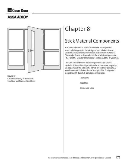
/
Ceco Door Products manufactures stick component Ceco Door Products manufactures stick component

Ceco Door Products manufactures stick component - PDF document

erica
erica . @erica
Follow
346 views
Uploaded On 2021-08-07

Ceco Door Products manufactures stick component - PPT Presentation

175Chapter 8material that permits the design of special door frame and lite arrangements from stock and custom materials Two major frame series make up these stick components They are the Standard Fra ID: 858597

frame 148 stick figure 148 frame figure stick components mullion type series weld transom bar rabbet door steel 149

Share:

Link:

Embed:

Download Presentation from below link

Download Pdf The PPT/PDF document "Ceco Door Products manufactures stick co..." is the property of its rightful owner. Permission is granted to download and print the materials on this web site for personal, non-commercial use only, and to display it on your personal computer provided you do not modify the materials and that you retain all copyright notices contained in the materials. By downloading content from our website, you accept the terms of this agreement.


Presentation Transcript

1 175 Chapter 8 Ceco Door Products manufac
175 Chapter 8 Ceco Door Products manufactures stick component material that permits the design of special door, frame, and lite arrangements from stock and custom materials. Two major frame series make up these stick components. They are the Standard Frame (SU) series and the (SQ) series. The versatility of these stick components and Ceco’s Arch-Tech frame heads provides the architect or engineer an opportunity to add zest and vitality to their designs. A continuous wall of door

2 , frame and glass lite designs are poss
, frame and glass lite designs are possible with this stick component material. Transoms Borrowed Lites Stick Material Components Figure 8-1 Ceco Door Entry System with Sidelites and Narrow Lite Door Ceco Door Commercial Steel Door and Frame Correspondence Course 176 (SU) Series Frame Profile Series (SU) Stick Components The series SU (Standard Unequal Rabbet) stick components are manufactured at the Ceco Door Tennessee manufacturing facility. They are made of cold rolled or A60 hot-dip

3 ped galvannealed, 16 gage steel, in 10&
ped galvannealed, 16 gage steel, in 10’ - 4” stick lengths. These stick components are process cleaned, dipped in a rust prohibitive primer paint, and oven baked for optimum protection. SU stick components are available in stock frame depths that include 4 - 3/4”, 5 - 3/4”, 6 - 3/4”, 7 - 3/4”, and 8 - 3/4”. These depths are stocked in the factory warehouse and ASSA ABLOY Service Centers. Unequal frame rabbets are standard on the SU frame stick profile

4 dimensions. SU series hinge jambs an
dimensions. SU series hinge jambs and lock jamb sticks are available with 1” and 2” frame faces. SU plain sticks are available in 1”, 2”, and 4” faces. Consult the Ceco Price Book for other available SU stick components, such as 14 gage sill section in 8’ - 4” lengths. Figure 8-2 Series SU Stock Frame dimensions for a 1-3/4” Door 177 (SU) Transom Hinge Jamb (THJ) Series (THJ) Stick Components The series SU transom hinge jambs are made from cold

5 rolled or A60 hot-dipped galvannealed,
rolled or A60 hot-dipped galvannealed, 16 gage steel, in 10’-4” stick lengths. SU (THJ) stick components are available in stock frame depths that include 4-3/4”, 5-3/4”, 6-3/4”, 7-3/4” and 8-3/4”. These depths are stocked at the factory warehouse and ASSA ABLOY Service Centers. Figure 8-3 Transom Hinge Jamb 178 (SU) Transom Lock Jamb & Plain Stick Transom Lock Jamb (TLJ) The series (SU) 16 gage Transom Lock Jamb offers a 1 inch or 2 inch face, and ar

6 e made from cold rolled or A60 hot-dippe
e made from cold rolled or A60 hot-dipped galvannealed, 16 gage steel. It is prepared for a ANSI 4-7/8” high universal strike. The Ceco strike height is 41-13/16” from the frame floor end to the center of the strike prep. Stock depths are available in 4-3/4”, 5-3/4”, 6-3/4”, 7-3/4”, and 8-3/4”. The TLJ is designed for use with 1-3/4” doors. Plain Stick Components The series (SU) 16 gage Plain Stick Component offers a 1”, 2”, or 4” fa

7 ce, and are made from cold rolled or A60
ce, and are made from cold rolled or A60 hot-dipped galvannealed, 16 gage steel. Stock depths are available in 4-3/4”, 5-3/4”, 6-3/4”, 7-3/4”, and 8-3/4”. The stick component is designed for use with 1-3/4” doors. Figure 8-5 Stick Component with a 1” Face Figure 8-6 Stick Component with a 2” Face Figure 8-7 Stick Component with a 4” Face Figure 8-4 Transom Lock Jamb 179 (SU) Standard Stick Components Hat Section Stick Components The 16 gage, cold

8 rolled or A60 galvanneled steel hat sec
rolled or A60 galvanneled steel hat section is used to create a stop, soffit and rabbets on both sides of a frame, creating a mullion. A common application is when a hat is used to create a stop for the glass installed in a partial Sidelite opening. In this case the hat would be spot welded into the back side of a frame stick. It comes in 10’ - 4’ lengths and is available in stock depths of 4-3/4”, 5-3/4”, 6-3/4”, 7-3/4”, and 8-3/4”. The hat section i

9 s also available from production in oth
s also available from production in other depths. Cased Opening The 16 gage cold rolled or A60 galvannealed steel, series (SU) cased opening offers a 1 inch face or 2 inch face. Stock depths are available in 4-3/4”, 5-3/4”, 6-3/4”, 7-3/4”, and 8-3/4”. Figure 8-8 Hat Section Figure 8-8A Hat Section Figure 8-9 Cased Opening Chapter 8 - Stick Component Materials Ceco Door Commercial Steel Door and Frame Correspondence Course Ceco Door Commercial Steel Door and Frame C

10 orrespondence Course 180 (SU) Universal
orrespondence Course 180 (SU) Universal Sidelite - Sill Stick Component Sill Stick Material Components The 14 gage sill pieces are stocked in 8’ - 4” lengths. Shipped in 4 pieces: the cap, two base sides, and a bracing strap. The cap width varies to create different frame depths. The table below indicates the part numbers for each cap width and the final frame depth. The face is available in standard 8-5/8”. Two piece Sill Sections are also available from production with f

11 aces over 4” up to and including 12
aces over 4” up to and including 12”, and in other gages. Figure 8-10 (SU) Sill Section Figure 8-11 Frame Sill Base PART NO. CAP WIDTH FRAME DEPTH FSC834 5-1/4 8-3/4” Depth FSC734 4-1/4 7-3/4” Depth FSC634 3-1/4 6-3/4” Depth FSC534 2-1/4 5-3/4” Depth FSC434 1-1/4 4-3/4” Depth 181 (SU) Mullion (CMT) Series (CMT) Mullion The series (CMT) mullions are manufactured at the Ceco Door Tennessee manufacturing facility. They are made from colled rolled or A60 hot-d

12 ipped galvanealed, 16 gage steel, in 10
ipped galvanealed, 16 gage steel, in 10’ - 4” stick lengths. These mullion stick components are process cleaned, dipped in a rust prohibitive primer paint, and oven baked for optimum protection. (CMT) mullion plain stick, lock and hinge jambs are available in stock frame depths that include 4-3/4”, 5-3/4”, 6-3/4”, 7-3/4” and 8-3/4” with a 2” face. The mullion strike is prepared for ANSI 4-7/8” high (universal) strike, and is located at 41-13/

13 16" to centerline up from the floor end
16" to centerline up from the floor end. The hinge mullion is prepared for 4-1/2” x .134 standard weight hinges. Figure 8-12 Series SU CMT Hinge Jamb Figure 8-12A Series SU Lock Strike Mullion Figure 8-13 “C” Mullion Profile 182 (SQ) Series Frame Profile Series SQ and SQ8 Series SQ (Standard Equal Rabbet) and SQ8 (for 1-3/8” doors) frame sticks are designed to satisfy those occasions when SU stick components should not be used. These component sticks are made to order

14 on a job-to-job basis and are not norma
on a job-to-job basis and are not normally stocked. They are made of cold rolled or A60 galvanealed steel and have a rust prohibitive prime paint coat. They have equal rabbeted frame profiles and are manufactured in 16, 14, and 12 gage, and are furnished in 10’-0” lengths. SQ stick components are made in both single and double rabbet profiles plus custom frame profiles. Single rabbet profiles are furnished in 3” to 6” frame depths and double rabbet profiles are furn

15 ished in 4-5/8” to 14” frame d
ished in 4-5/8” to 14” frame depths. Face dimensions are 1” and 2” for hinge jambs, lock jamb, and plain stick components. Consult the Ceco Price Book for a more complete listing of frame depth and face ranges. Figure 8-14 Series SQ Frame Profile Double Rabbet Profile Figure 8-14A Series SR Single Rabbet Profile Figure 8-14B Series SC Cased Open Profile 183 (SQ) Transom Hinge Jamb & Transom Lock Jamb The (SQ) series of stick components is just like the (SU) series with

16 the exception of being equal rabbet and
the exception of being equal rabbet and 10'-0" in overall length. The sticks are available in single and double rabbets. The SQ stick components are available in 16, 14, and 12 gage cold rolled or A60 galvannealed steel. The double rabbet SQ transom hinge jamb (THJ) and transom lock jamb (TLJ) is available in 4-5/8” to 14” depths. The single rabbet SR transom hinge jamb (THJ) and transom lock jamb (TLJ) is available in 3” to 6” depths. Both are available in 1”

17 and 2” faces and are designed to u
and 2” faces and are designed to use with 1-3/4” doors. Figure 8-15 SQ Double Rabbet Transom Hinge Jamb (THJ) Figure 8-16 SR Single Rabbet Transom Lock Jamb (TLJ) 184 (SQ) Series Stick Components Plain Sill Stick Components The (SQ) series sill stick component is made of 16, 14, or 12 gage cold rolled or A60 hot dipped galvannealed steel. It is available in double or single rabbets with faces varying from 2-1/8” to 12”. The single rabbet sill depth is 3” to 6”

18 ;, while the double rabbet sill depth i
;, while the double rabbet sill depth is 4-5/8” to 14”. Both are available in 10'-0" lengths. Figure 8-17 Double Rabbet Stick Components Figure 8-18 SR Single Rabbet Stick Components 185 (D) and (B) Series Mullion Sticks Mullions come in two additional styles, the DMT (D series mullion) and the BMT(B series mullion) section. The DMT is composed of two 10’-0” sections that slide together to interlock at the stops. Each section represents half of the mullion. Once the

19 unit is assembled, it should be spot we
unit is assembled, it should be spot weld - ed. The DMT mullion is available in single or double rabbets, and in 16, 14, or 12 gage cold rolled or A60 hot dipped gal - vannealed steel. The face is available in 1” to 12” , and depths are available from 3" to 6" (single rabbet) and 4-5/8” to 14” (double rabbet). There is a wide array of applications for this product, usually defined by the architect. The BMT is also composed of two 10'-0” sticks fit together. It

20 is composed of a hat section and a fram
is composed of a hat section and a frame section. Once the two sections are assembled, they should be spot welded. The face is available in 1” to 12”, and depths are available from 4-5/8” to 14”. The BMT is available in 16, 14, or 12 gage cold rolled or A60 hot dipped galvannealed steel. Figure 8-19 “D” (DMT) Mullion Stick Figure 8-20 “D” Mullion Profile Figure 8-21 “B” (BMT) Mullion Stick Figure 8-22 “B” Mullion Profile 186 Oth

21 er Series Stick Components Cased Opening
er Series Stick Components Cased Opening Stock Sill Section BQ Stick Section Figure 8-23 Cased Open Section Figure 8-25 Stock Sill Section Figure 8-24 Before Drywall Stick Section Co ld Rolled or A60 Galvannealed8-5/8” 187 (SU or SQ) Series Special Corner Stick Components 2-Way Mullion Three Way Mullion Four Way Mullion Figure 8-26 Corner Assembly Figure 8-27 Corner Assembly Figure 8-28 Corner Assembly Optional connection of components shown using closure clip when wrapping an existing

22 steel column/tube. 188 Custom Frame Prof
steel column/tube. 188 Custom Frame Profiles - Stick Compnents Figure 8-29 Custom Frame Profiles 189 T-2 Type Weld Figure 8-33 T-2 Type Weld Welding Type T-2, “Outside Face Weld Only” • Standard KD Frame components from stock with corner tabs • No saw cutting required 190 T-3 Type Weld Figure 8-34 T-3 Type Weld Welding Type T-3, “Outside Face Weld and FullWeb Weld” • Standard KD Frame components from stock with corner tabs • No saw cutting

23 required 191 V-2 Type Weld Figure 8-36 V
required 191 V-2 Type Weld Figure 8-36 V-2 Type Weld Welding Type V-2, “Inside Face Weld Only” • Die-cut frame components • No corner tabs • No saw cutting required 192 V-3 Type Weld Figure 8-37 V-3 Type Weld Welding Type V-3, “Inside Face Weld and Full Web Weld” • Die-cut frame components • No corner tabs • No saw cutting required 193 Reserved for Future Use 194 V-5 Type Weld Figure 8-39 V-5 Type Weld Welding Type V-5, “Inside Face Weld a

24 nd Full Web Weld” • Miter-sawe
nd Full Web Weld” • Miter-sawed frame components • No corner tabs 195 V-6 Type Weld Figure 8-41 V-6 Weld 196 V-8 Type Weld Figure 8-42 V-8 Type Weld Welding Type V-8, “Butted Condition – Junction of a Mullion or Transom Bar to a Vertical or Head – Outside Face Weld Only” • Mullion or transom bar coped to fit jamb or head 197 V-9 Type Weld Figure 8-43 V-9 Type Weld Welding Type V-9, “Butted Condition – Junction of a Mullion or Transom Bar to a

25 Vertical Mullion or Impost – Outsi
Vertical Mullion or Impost – Outside Face Weld Only” • Mullion or transom bar coped to fit vertical mullion or impost 198 Welded Single Frame/Sidlite Unit Figure 8-44 Partial Sidelite Frame 199 Welded Single Frame/Transom/Sidelite/Sill Figure 8-45 Transom Sidelite Frame 200 Splined Frames There are certain times when it becomes impractical to manufacture a Sidelite transom frame as one unit. It normally i

26 s when the unit is to large for shipping
s when the unit is to large for shipping or so large that handling could cause damage. When a unit becomes too large, it must be broken down into several parts. Consider breaking the frame when the overall size exceeds 8’0” in both directions. The frame jamb pieces at the points being separated would have 1” faces in the frame shown by Figure 8-47. They would be held together by use of the splines. The “U” shaped part of the spline fits over the two backbends

27 of the frame section and are then drive
of the frame section and are then driven into position (see figure 8-48). Four splines are used on openings 7’6” to 8’0” and five on up to 9’-0” units. They should be located at about 3” from each end and spaced every 2 feet. Figure 8-47 Oversized Splined Frames 201 Spline Connection Details 1) One Spline Required for Every Two feet in Impost Height or any fraction thereof. 2) Provide Access at Top Impost for Insertion of Spline. Imp

28 ost. 4) Drive Splines Into Frame Sectio
ost. 4) Drive Splines Into Frame Sections as Required. Figure 8-48 Splined Impost Note: the seam where the two frame sections are joined together in the field must be filled by bondo or weld and bondo. 202 Frame Spreader Bars Spreader Bar Profile This bar is not to be used for installation. A wood spreader is to be used for maintaining proper spacing between jambs. (See the ANSI/SDI A250.11 “Recommended Erection Instruc - tions for Steel Frames”) This spreader bar is a shippin

29 g and handling aid only. Spreader Bar Le
g and handling aid only. Spreader Bar Length Length of spreader bar is equivalent to door opening width dimension. Standard spreader stock length is 10’-0”. Spreader Bar Quantity and Location Single rabbet and double rabbet frames not exceeding 6” depth should have (1) spreader bar attached to the frame rabbet. (see figure 8-49) Double rabbet frames with a depth greater than 6” and all double swing frames should have (2) spreader bars attached, 1 to each frame rabb

30 et (see figure 8-50). Spreader Bar Attac
et (see figure 8-50). Spreader Bar Attachment Verify spreader bar length by checking to see that the length is equivalent to the door opening width dimension at the head. Place the spreader bar at the bottom of the door open - ing and tack weld in place. Strength of welds should be such that the spreader bar remains in place during transit and that the spreader bar can be removed when required (by means of a sharp hammer-blow) without incurring frame damage. Figure 8-48a Spreader Bar Figu

31 re 8-49 Spreader Bar in Frame Rabbet Fi
re 8-49 Spreader Bar in Frame Rabbet Figure 8-50 Spreader Bar in Frame Rabbets 203 Glazing Bead Standard Glazing Bead The standard glazing bead is a steel channel 5/8” wide x 5/8” high x 10’-0” long and is stocked at the Ceco factory and ASSA ABLOY Service Centers. It is attached by using a #8 - 18 x 1-1/2” phillips oval head TEK screw spaced 8” on center. The advantage of the TEK screw is that it drills its own hole. Thermopane Glazing Bead The standar

32 d bead fits the frame section well, ther
d bead fits the frame section well, therefore, to accommodate 1” thick glass, the standard 5/8” wide x 5/8” high bead can be used in the 1-15/16” rabbet. Figure 8-50A Standard Glazing Bead 4-1/2”4-1/2” 18 gage A60 Galvannealed Steel 204 Glazing Bead Details Figure 8-51 Glazing Bead Details Notes: from each end to the first holes are equal • Cut the horizontal beads to fit the full width of opening • Cut the vertical beads to fit between horizo

33 ntal beads • A standard stock leng
ntal beads • A standard stock length of glazing bead is 10’-0” When Ceco installs the glazing bead in welded frames, the bead will be set hard against the stop of the frame with one screw unless specified otherwise on the order. When bead is requested to be set with a specific pocket width, pocket size must be provided. Pocket Size 205 Removable Transom Bar Connection Figure 8-52 Removable Transom Bar • Transom bar is cut to length • Vertical jambs are notched as s

34 hown • Angle clips are welded to tr
hown • Angle clips are welded to transom bar • Reinforcing plates are welded to inside of jamb soffit • Transom bar is fit into notched jambs and transfer drilled thru angle clip using drill #7, then tapped for 1/4 - 20 MS 206 Frame Splices When a unit has components longer than the standard 10’-4” or 10'-0", it becomes necessary to splice two frame pieces together. Closer reinforcing should be used to help dissipate the heat from welding. Without this backing

35 , the frame section would have a tenden
, the frame section would have a tendency to bow or wrap. Splices should be made at the intersection of a mullion or transom bar if at all possible for structural support. 8-53 Frame Splice Connections using closer plates 207 Closer Reinforcement Figure 8-53A Sleeve Type Closer Reinforcement 208 ern T�TTs� PT RS ��ROW �P �S� �PO� dndrxst xggfsK Plate Reinforcement for Closers Figure 8-54A Pl

36 ate Type Closer Reinforcement Regular Ar
ate Type Closer Reinforcement Regular Arm Closer Mounting S1 Figure 8-54B Plate Type Closer Reinforcement Parallel Arm Closer Mounting S2 Figure 8-54C Plate Type Closer Reinforcement Corner Bracket Closer Mounting S3 Figure 8-54D Plate Type Closer Reinforcement Top Jamb Closer Mounting S4 REPLACE PICTURES 209 Plate Reinforcement for Closers, Surface Bolts, and Rim Strike Figure 8-55A Plate Type Closer Reinforcement Parallel Arm Closer Mounting S5 Figure 8-55C Plate Type Closer Reinforcement I

37 nswing Door: Surface Bolts S7 Figure 8-5
nswing Door: Surface Bolts S7 Figure 8-55D Plate Type Closer Reinforcement Rim Type Panic Device Mounting R Figure 8-55B Plate Type Closer Reinforcement Outswing Door Surface Bolts, Surface Vertical Rod Surface Strikes And Removable Hardware Mullion SR6 ST�P�RSSTOTPTWJMAWOARB�T�T OT WNSWPR OT OT F RO T�TTN �SS FOOR ANF FOOR OF 210 Removable Impost Mullion Figure 8-59 Removable Impost Mullion 211 Stick Component Fram

38 e Intersections Figure 8-58 Stick Compon
e Intersections Figure 8-58 Stick Component Frame Intersections 212 Stick Component Frame Intersections Figure 8-60 90 o Corner Connection of Impost Vertical corner design when a closed mullion can’t be used. e.g. to wrap an existing steel column. Chapter 8 - Stick Component Materials Ceco Door Commercial Steel Door and Frame Correspondence Course Chapter 8 - Stick Component Materials Ceco Door Commercial Steel Door and Frame Correspondence Course Ceco Door Commercial Steel Door and Fr