/
Connection Design for Steel Structures Connection Design for Steel Structures

Connection Design for Steel Structures - PDF document

faustina-dinatale
faustina-dinatale . @faustina-dinatale
Follow
467 views
Uploaded On 2016-04-21

Connection Design for Steel Structures - PPT Presentation

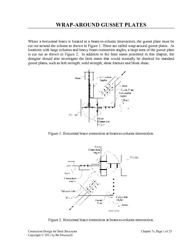
Where a horizontal brace is located at a beamtocolumn intersection the gusset plate must be cut out around the column as shown in Figure 1 These are called wraparound gusset plates At locations ID: 286891

Where horizontal brace

Share:

Link:

Embed:

Download Presentation from below link

Download Pdf The PPT/PDF document "Connection Design for Steel Structures" is the property of its rightful owner. Permission is granted to download and print the materials on this web site for personal, non-commercial use only, and to display it on your personal computer provided you do not modify the materials and that you retain all copyright notices contained in the materials. By downloading content from our website, you accept the terms of this agreement.


Presentation Transcript

Connection Design for Steel Structures Chapter 7e, Page 1 of 25 Copyright © 2011 by Bo Dowswell Where a horizontal brace is located at a beam-to-column intersection, the gusset plate must be cut out around the column as shown in Figure 1. These are called wrap-around gusset plates. At locations with large columns and heavy beam connection angles, a large area of the gusset plate is cut out as shown in Figure 2. In addition to the limit states presented in this chapter, the designer should also investigate the limit states that would normally be checked for standard gusset plates, such as bolt strength, weld st Figure 1. Horizontal brace connection at beam-to-column intersection. Figure 2. Horizontal brace connection at beam-to-column intersection. Connection Design for Steel Structures Chapter 7e, Page 4 of 25 Copyright © 2011 by Bo Dowswell plates reached full plasticity before buckling. A typical plot of the elastic and inelastic stresses is shown in Figure 6 for a finite element model loaded to its failure load. The theoretical stresses, which were calculated using simple beam theory, are also shown in the figure. The proposed design method is based on an elastic bending stress distribution. The in-plane flexural deformation of Specimen 2T is shown in Figure 7. -80-60-40-20020406080Flexural Stress (ksi) Elastic Theoryresses in gusset plate legs. Figure 7. In-plane deformation of Specimen 2T. The bending moments at the critical sections of the plate are 112 M (3a) 221 M (3b) and are the components of the factored brace load, and are the cutout dimensions at each leg, as shown in Figure 2. The nominal moment capacity of each leg is Connection Design for Steel Structures Chapter 7e, Page 5 of 25 Copyright © 2011 by Bo Dowswell (4a) (4b) For the design to be adequate, the following must be satisfied: (5a) (5b)Sometimes wrap-around gusset plates have the interior corner cut on a diagonal as shown in Figure 8b in an effort to increase their capacity. The test Specimens 8 and 10, shown in Figure 8, were identical except for the diagonal cut on Specimen 10. The tests and finite element models showed that the average capacity for Specimen 10 was 22 percent higher than the average capacity for Specimen 8. Figure 9 shows the stress contour plots for Specimen 10. Figure 9a shows the normal stresses in the 9b shows the normal stresses in the y-direction. The moment capacity at cross sections and should be checked at each leg using Equations 3, 4, and 5. Calculations show that the flexural stresses in the x-direction at are 2.40 times the stresses at Section . The finite element stresses in Figure 8a confirm this. Similarly, Figure 8b confirms that Section a-a controls the design for the stresses in the y-direction. The calculated flexural stresses in the y-direction are 89% higher at Section a-a than they are at Section a. Specimen 8 b. Specimen 10 Figure 8. Details of Specimens 8 and 10. Connection Design for Steel Structures Chapter 7e, Page 7 of 25 Copyright © 2011 by Bo Dowswell LATERAL-TORSIONAL BUCKLINGDue to the flexural stresses in the gusset plate legs, they are subject to lateral-torsional buckling. Tests showed that the flexural stresses in the legs can cause lateral-torsional buckling, even if the brace is loaded in tension. The permanent deformation in tension and compression specimens can be seen in Figures 10 and 11 respectively. All of the specimens had a permanent out-of-plane deformation at the plate edges with flexural compression stresses. The out-of-plane deformation was accompanied by twisting of the gusset plate legs, indicating a lateral-torsional buckling failure. The finite element models are shown in Figures 12 and 13 for tension and compression loads respectively. Figure 10. Tension Specimen 2T after test. a. Specimen 4C b. Specimen 7C Figure 11. Compression Specimens Connection Design for Steel Structures Chapter 7e, Page 9 of 25 Copyright © 2011 by Bo Dowswell Where is the modulus of elasticity and is the shear modulus. The design buckling capacity moment at each gusset plate leg. cru (10a) cru (10b) M and M are determined with Equations 3a and 3b respectively, and = 0.9 for lateral-torsional buckling. To determine the buckling length, to be used in Equation 9, the buckled shape of the specimens and finite element models was observed. For the specimens loaded in tension, the inside edges buckled farther than the outside edges. This behavior was expected because the maximum compressive flexural stresses are on the inside edges, at the reentrant corner. The specimens loaded in compression buckled farthe Figure 14 shows how this behavior affects the buckling length of the legs. The plate in Figure 14a was loaded in tension. The buckling of each leg is restrained at the reentrant corner and the buckling length, is the length of the cutout. The following buckling lengths can be used when the plate is loaded in tension: for Leg 1, and for Leg 2. For plates loaded in compression, as shown in Figure 14b, the buckling length ends approximately at the center of the adjacent leg. For design purposes, the following buckling lengths can be used when the plate is loaded in compression: Led 211 L for Leg 2. Connection Design for Steel Structures Chapter 7e, Page 11 of 25 Copyright © 2011 by Bo Dowswell Table 1. Calculated capacities. minFailure 2T 33.12 145.7 105.94 33.12 Y 6T 31.79 101.7 43.48 31.79 Y 8T 46.00 155.8 141.92 46.00 Y 9T 35.77 115.6 84.90 35.77 Y 10T 68.00 204.0 145.27 68.00 Y 1C 39.52 115.9 56.80 39.52 Y 2C 32.87 144.6 73.46 32.87 Y 3C 36.14 115.6 96.08 36.14 Y 4C 23.12 101.7 16.32 16.32 B 5C 25.84 82.70 22.43 22.43 B 6C 31.79 101.7 27.83 27.83 B 7C 45.07 144.2 124.29 45.07 Y 8C 46.48 157.4 94.73 46.48 Y 9C 36.71 118.6 69.46 36.71 Y 10C 67.47 202.4 91.83 67.47 Y calculated elastic bending capacity calculated shear capacity calculated lateral-torsional buckling capacity min minimum of The experimental results are summarized in Table 2. is the experimental yield load, f is the yield load from the finite element models, and f yP Connection Design for Steel Structures Chapter 7e, Page 13 of 25 Copyright © 2011 by Bo Dowswell EXAMPLES LRFD. The bottom of the brace is down 14¼ in. from the top of steel. ps tension or compression Gusset plate thickness: Gusset plate material: A572 Grade 50 Clip angle material: A36 W and WT material: A992 Bolts: ¾-in. diameter A325N Weld: 70 ksi AWS Holes: Standard -in. diameter Figure. E1-1. Connection for Example 1. Brace-to-Gusset Plate Bolt shear fracture From Manual Table 7-1, the design shear strength for each bolt, 15.9kipsbolt . Connection Design for Steel Structures Chapter 7e, Page 16 of 25 Copyright © 2011 by Bo Dowswell 0.752132kips198kips35 kipsI !Block shear of gusset plate Due to the geometry of the gusset plate, block shear can occur in compression, where the shear planes extend into the cutout. For compression loads, the edge distances in the direction of load are 6.44 in. and 2.64 in., and for tension loads, the edge distances are 3.11 in. and 4.41 in. The sum of edge distances is smaller for tension loads; therefore, this will result in the lowest block 26in.3.11in.+4.41in.38 in.7.32in  7.32in.22.5holes78in.38 in.5.68in  5.5in.212hole78in.38 in.1.73in  1.0 0.75 I 0.60.6nunvbsuntygvbsunt FAUFAFAUFA d0.6(0.6)(65 ksi )(5.68 in.)(1.0)(65 ksi)(1.73 in.)334 kipsunvbsuntFAUFA  0.6(0.6)(50 ksi)(7.32 in.)(1.0)(65 ksi)(1.73 in.)332 kipsygvbsuntFAUFA  0.75332kips249kips35 kipsI !Leg Connecting to W14 1.00.61.00.650ksi10in.38in.112kipsVFdtI 112kips22.5kips 38in.10in.0.90.950ksi281kipin.I ˜ 11222.5kips12in.270kipin.MPe ˜ Connection Design for Steel Structures Chapter 7e, Page 18 of 25 Copyright © 2011 by Bo Dowswell 16.5 kips / bolt2.33 bolts38.4 kips22.5 kipsI !For bolt bearing, the effect of eccentricity must be accounted for; therefore, the effective number of bolts, = 2.33, will be used from Manual Table 7-7. The edge distance perpendicular to the beam axis is 126.73 in.1in.1.62 in.  1.62 in.121316 in.1.21 in.  Between the bolts, 3 in.1316 in.2.19 in.  1.21in.2.19 in.; use 1.21 in. 0.751.21.21 in.0.385 in.65ksi0.752.434 in.0.385 in.65 ksiI d27.2 kips / bolt 33.8 kips / boltI d. Use 27.2 kips / bolt 27.2 kips / bolt2.33 bolts63.4 kips22.5 kipsI ! 0.750.638in.10 in.(3)(7/8 in.)65ksi80.9kips22.5 kips  !Flexural fracture of gus 21.50in.2.12in.38in.4.22in.1.56in.38in.7.32in.net=  65ksi7.32in.476kip-in.nunetMFZI 22.5kips1in.39.4kip-in.476kip-in.Block shear of gusset plate Connection Design for Steel Structures Chapter 7e, Page 20 of 25 Copyright © 2011 by Bo Dowswell 603kip-in.221kip-in.Bolt shear fracture The gage in the outstanding leg of the clip angle is 2 in.; therefore, the bolts are subject to an eccentricity of 2 in. From Manual Table 7-1, the available shear strength for each bolt, 15.9kipsboltFrom Manual Table 2.23bolts15.9kipsbolt35.5kip�s 26.8kipsI 1.00.638in.9in.36ksi72.9kips26.8 kipsI ! 0.750.638in.9 in.(3)(7/8 in.)58ksi62.4kips26.8 kipsI  !Manual Table 8-8 with the load angle equal zero 3in.12in.3.00 in.  9in. 3.00in.9in. = 0.0670 Interpolated from Table 8-8 0.06709in.0.603in. 3in.0.603in.2.90in.  2.90in.9in. Connection Design for Steel Structures Chapter 7e, Page 22 of 25 Copyright © 2011 by Bo Dowswell 0.752.434in.0.300 in.65 ksi26.3kipsI 26.3 kips / bolt2.23 bolts58.6 kips kipsI ! in.9in.7.59in.= 50ksi7.59in.380kip-in.MFZI 26.8kips2in.53.6kip-in.380kip-in. 21.50in.2.12in.38in.3.97in.1.06in.38in.5.54in.net=  65ksi5.54in.360kip-in.nunetMFZI 26.8kips2in.53.6kip-in.360kip-in. 7in.38 in.2.81in 7in.2.5holes78in.38 in.1.99in  1in.12hole78in.38 in.0.398in  1.0 0.75 I 0.60.6nunvbsuntygvbsunt FAUFAFAUFA d0.6(0.6)(58 ksi )(1.99 in.)(1.0)(58 ksi)(0.398 in.)92.3 kipsunvbsuntFAUFA  0.6(0.6)(36 ksi)(2.81 in.)(1.0)(58 ksi)(0.398 in.)83.8 kipsygvbsuntFAUFA  Connection Design for Steel Structures Chapter 7e, Page 24 of 25 Copyright © 2011 by Bo Dowswell 113kips32.1kipsShear in Leg 2 Shear capacity will be analyzed at a plane immediately beyond the clip angle leg. The leg width at this location is, 10in.4in.3.5in.8.25in.11.7in  1.00.61.00.650ksi11.7in.0.375in.132kipsVFdtI 132kips38.3kips 0.375in.10in.0.90.950ksi281kipin.I ˜ 11232.1kips8in.257kipin.MPe ˜281kipin.257kipin.˜!˜ (Case 1: Immediately be 10in.4in.3.5in.8.25in.11.7in  0.375in.11.7in.0.90.950ksi385kipin.I ˜ 22138.3kips3.5in.134kipin.MPe ˜385kipin.134kipin.˜!˜ (Case 2: End of diagonal cut) 0.375in.14in.0.90.950ksi551kipin.I ˜ 22138.3kips8.25in.316kipin.MPe ˜