/
DELight Programming Guide September  Quiescent Draw  mA LED Draw  mA maximum apiece Avoid DELight Programming Guide September  Quiescent Draw  mA LED Draw  mA maximum apiece Avoid

DELight Programming Guide September Quiescent Draw mA LED Draw mA maximum apiece Avoid - PDF document

faustina-dinatale
faustina-dinatale . @faustina-dinatale
Follow
515 views
Uploaded On 2014-11-10

DELight Programming Guide September Quiescent Draw mA LED Draw mA maximum apiece Avoid - PPT Presentation

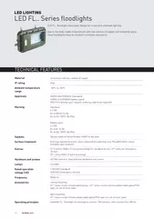
Input Voltage 6V recommended 472v nominal Runs off BEC power make sure your BEC can handle i t LED Brightness Up to 15 lumens Maximum Controller Commands 94 Interface USB Operating System Windows 98 2k 2k3 NT ME XP Vista Dimensions DELight Controlle ID: 9430

Input Voltage recommended

Share:

Link:

Embed:

Download Presentation from below link

Download Pdf The PPT/PDF document "DELight Programming Guide September Qui..." is the property of its rightful owner. Permission is granted to download and print the materials on this web site for personal, non-commercial use only, and to display it on your personal computer provided you do not modify the materials and that you retain all copyright notices contained in the materials. By downloading content from our website, you accept the terms of this agreement.


Presentation Transcript

DELight Programming Guide September 2008 Quiescent Draw: 15 mA LED Draw:150 mA maximum apiece Avoid connecting more than one LED to the controller when it’s being powered by your computer. Input Voltage: 6V recommended, 4-7.2v nominal Runs off BEC power; make sure your BEC can handle it! LED Brightness: Up to 15 lumens Maximum Controller Commands: 94 Interface: USB Operating System: Windows 98, 2k, 2k3, NT, ME, XP, Vista Dimensions: DELight Controller: 28 x 22 x 5mm; 31cm pigtail; 6mm header; 6g 1.1” x .9” x .2”; 1’ pigtail; .25” header; .2 oz LEDs: 10 x 5 x 3mm board; 61cm pigtail; 3g .4” x .2” x .1” board; 2’ pigtail; .1 oz General Description: The DELight is a programmable lighting controller designed for some of the greatest ease of use on the market. DELight supports eight channels of LEDs. Channels 1-4 can output 250mA and can be configured for brightness, timing, stick position, signal loss, hysteresis and more. Channels 5-6 can output up to 2 amps and can be programmed for all of those but brightness, or make another auxiliary switch. Channels 7-8 can also output 2A; anything hooked in to them will be on as long as it has power, so they make a good test of whether or not the DELight is receiving power and are handy for navigation lights and night flying. The DELink (included in the Starter Kit) includes everything necessary to transfer lighting programs from your computer to the controller. The DELink is connected to your computer through a USB port. The servo connector of the DELight Controller (that would normally hook into your receiver) goes to the Plug header of the DELink, matching servo colors. LEDs hook in as shown below, with the red wire facing the Controller label. Your computer’s USB hub may not be rated for a lot of current, so only connect one LED at once when powered via USB. DELink Software Installation The software for the DELight system is free to download and test, and is 7.7 MB. The interface is fully graphical, and we hope you will find it to be intuitive as well. It can be found at www.dimensionengineering.com/software/setup.exe . Starting the installation is as easy as running the downloaded file. Your firewall (or Windows Vista) may ask permission to allow DELink to install drivers. This is normal. DELink Software Use Commands on a given channel are divided into two tracks, Top and Bottom. Which is active at any given time depends on your throttle and the Trip Point. If your throttle or servo input (depending on where you plan to connect the DELight to your receiver) is above the channel’s Trip Point, the top track’s commands will be in effect for that channel; note that the trip point can be set to a different value for each channel. If your throttle or servo input is above every channel’s Trip Point, the top track commands of each channel will run across your entire setup. Turn Off Below creates in effect a third trip point, below which the lighting on that channel is completely deactivated. You could, for instance, set your lights to turn on at 25% and flash above 75% throttle via Turn Off Below 25%, Trip Point 75%. No Signal Default sets which track the selected channel will run should you lose radio signal for any reason. For instance, setting the default to bottom track you would see it quickly if the controller suddenly ran low-throttle light settings when your throttle stick is at 100%. Hysteresis determines how far beyond the actual trip point the throttle stick must be to trigger a lighting change, which is convenient for maneuvering close to the trip point without continually changing light settings. Note that this sets actual hysteresis via the controller. If you want settings to change immediately when your throttle stick passes the trip point, set this value to 0%. Light Color changes the color of the light as displayed in the Simulator. Max Current sets the amount of current given to a channel at 100% brightness. Dimension Engineering DELight LEDs can output up to 150mA, but if using third-party lights, find the maximum current they can allow. Brightness determines the percentage of maximum current the light on that channel receives. If your Max Current is set to 100 mA, for instance, 25% brightness will be 25 mA generating light. Time is the length of the command, allowing timed pulses, strobe lights or more. When the channel’s last command is completed, it will return to the first. Add creates another command at the end of the chain with the same settings as the one you have selected. Insert creates another command after the currently selected command, with the same settings as it. Delete removes a command. Zoom to Fit shows all the commands on that channel. Program collects data on the entire program you have made, sends it to an attached DELink and flashes it to the connected DELight Controller. Please wait to disconnect the DELight until it has completed programming. The Simulator gives an approximation of how the lighting setup will look. You can simulate loss of radio signal to see what happens if your radio encounters interference, hysteresis to give an indication of how far over the trip point you'll have to go to trigger a new pattern, and for intricate or fast designs, set it to display at 1/4 speed to see the timing shifts more clearly. The lighting channels are represented by the black squares. Click and drag any of the channel displays to form your own patterns. Mouse over a square to see which channel it corresponds to, and right click on it to change its image from the defaul. The background can likewise be changed by right clicking it and selecting Change Background, which you can then fill with any image you like. Updating the DELink Software Every now and then, Dimension Engineering will have a patch to the software for upgraded functionality or bug fixes. If Options -� Automatically Check for Updates is enabled, you will occasionally be prompted to install one. Disabling automatic updates will require you to download a new version of the software each time you wish to update it.