/
1 Chapter 12: Structures & Properties of Ceramics 1 Chapter 12: Structures & Properties of Ceramics

1 Chapter 12: Structures & Properties of Ceramics - PowerPoint Presentation

giovanna-bartolotta
giovanna-bartolotta . @giovanna-bartolotta
Follow
503 views
Uploaded On 2015-10-02

1 Chapter 12: Structures & Properties of Ceramics - PPT Presentation

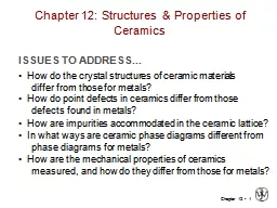
ISSUES TO ADDRESS How do the crystal structures of ceramic materials differ from those for metals How do point defects in ceramics differ from those defects found in metals ID: 147709

callister amp adapted rethwisch amp callister rethwisch adapted fig structure cation crystal charge cations structures ceramics ionic anion impurity

Share:

Link:

Embed:

Download Presentation from below link

Download Presentation The PPT/PDF document "1 Chapter 12: Structures & Propertie..." is the property of its rightful owner. Permission is granted to download and print the materials on this web site for personal, non-commercial use only, and to display it on your personal computer provided you do not modify the materials and that you retain all copyright notices contained in the materials. By downloading content from our website, you accept the terms of this agreement.


Presentation Transcript

Slide1

1

Chapter 12: Structures & Properties of Ceramics

ISSUES TO ADDRESS...

• How do the crystal structures of ceramic materials differ from those for metals?

• How do point defects in ceramics differ from those defects found in metals?

• How are impurities accommodated in the ceramic lattice?

• How are the mechanical properties of ceramics measured, and how do they differ from those for metals?

In what ways are ceramic phase diagrams different from

phase diagrams for metals

?Slide2

2

• Bonding:

-- Can be ionic and/or covalent in character. -- % ionic character increases with difference in electronegativity of atoms.

Adapted from Fig. 2.7, Callister & Rethwisch 8e. (Fig. 2.7 is adapted from Linus Pauling,

The Nature of the Chemical Bond, 3rd edition, Copyright 1939 and 1940, 3rd edition. Copyright 1960 byCornell University.)

• Degree of ionic character may be large or small:Atomic Bonding in Ceramics

SiC: small

CaF

2

: largeSlide3

3

Ceramic Crystal Structures

Oxide structuresoxygen anions larger than metal cations

close packed oxygen in a lattice (usually FCC)cations fit into interstitial sites among oxygen ionsSlide4

4

Factors that Determine Crystal Structure

1. Relative sizes of ions

– Formation of stable structures: --maximize the # of oppositely charged ion neighbors.

Adapted from Fig. 12.1, Callister & Rethwisch 8e.

-

-

-

-

+

unstable

-

-

-

-

+

stable

-

-

-

-

+

stable

2.

Maintenance of

Charge Neutrality

:

--Net charge in ceramic

should be zero.

--Reflected in chemical

formula:

CaF

2

:

Ca

2+

cation

F

-

F

-

anions

+

A

m

X

p

m, p values to achieve charge neutrality

Charge

C. G. Slide5

5

• Coordination # increases with

Coordination # and Ionic Radii

Adapted from Table 12.2,

Callister & Rethwisch 8e.

2

r

cation

r

anion

Coord

#

< 0.155

0.155 - 0.225

0.225 - 0.414

0.414 - 0.732

0.732 - 1.0

3

4

6

8

linear

triangular

tetrahedral

octahedral

cubic

Adapted from Fig. 12.2,

Callister & Rethwisch 8e.

Adapted from Fig. 12.3,

Callister & Rethwisch 8e.

Adapted from Fig. 12.4,

Callister & Rethwisch 8e.

ZnS

(zinc blende)

NaCl

(sodium

chloride)

CsCl

(cesium

chloride)

r

cation

r

anion

To form a stable structure, how many anions can

surround around a cation?

UNIT CELL- ATOM RATIO

ION LOCATIONSSlide6

6

Computation of Minimum Cation-Anion Radius Ratio

Determine minimum rcation

/ranion for an octahedral site (C.N. = 6)

a = 2ranionSlide7

7

Bond Hybridization

Bond Hybridization is possible when there is significant covalent bonding

hybrid electron orbitals formFor example for SiCXSi = 1.8 and

XC = 2.5

~ 89% covalent bonding Both Si and C prefer sp3

hybridization

Therefore, for SiC, Si atoms occupy tetrahedral sitesSlide8

8

On the basis of ionic radii, what crystal structure would you predict for FeO?

• Answer:

based on this ratio,-- coord # = 6 because

0.414 < 0.550 < 0.732-- crystal structure is NaCl

Data from Table 12.3, Callister & Rethwisch 8e.

Example Problem:

Predicting the Crystal Structure of FeO

Ionic radius (nm)

0.053

0.077

0.069

0.100

0.140

0.181

0.133

Cation

Anion

Al

3+

Fe

2

+

Fe

3+

Ca

2+

O

2-

Cl

-

F

-Slide9

9

Rock Salt Structure

Same concepts can be applied to ionic solids in general.

Example:

NaCl (rock salt) structure

rNa = 0.102 nm

rNa/rCl = 0.564

cations (Na

+

) prefer octahedral

sites

Adapted from Fig. 12.2,

Callister & Rethwisch 8e.

r

Cl

= 0.181 nmSlide10

10

MgO and FeO

O

2-

r

O = 0.140 nmMg2+ rMg = 0.072 nm

rMg/rO = 0.514

cations prefer octahedral sites

So each Mg

2+

(or Fe

2+

) has 6 neighbor oxygen atoms

Adapted from Fig. 12.2,

Callister & Rethwisch 8e.

MgO and FeO also have the NaCl structureSlide11

11

AX Crystal Structures

Adapted from Fig. 12.3,

Callister & Rethwisch 8e.

Cesium Chloride structure:

 Since 0.732 < 0.939 < 1.0, cubic

sites preferredSo each Cs

+

has 8 neighbor Cl

-

AX–Type Crystal Structures include NaCl, CsCl, and zinc blendeSlide12

12

AX

2 Crystal Structures

Calcium Fluorite (CaF2) Cations in cubic sites

UO2, ThO2, ZrO2, CeO2

Antifluorite structure – positions of cations and anions reversed

Adapted from Fig. 12.5, Callister & Rethwisch 8e.

Fluorite

structure

UNIT CELL –TWO DIAGONALSSlide13

13

ABX

3 Crystal Structures

Adapted from Fig. 12.6, Callister & Rethwisch 8e.

Perovskite structureEx: complex oxide

BaTiO3CHARGE C.G. SEPARATE AT GEOMETRICAL CENTERSlide14

VMSE: Ceramic Crystal Structures

14Slide15

15

Density Computations for Ceramics

Number of formula units/unit cell

Volume of unit cell

Avogadro’s number

= sum of atomic weights of all anions in formula unit

= sum of atomic weights of all cations in formula unit

NUMBER OF CAT AND ANION WITHIN AN UNIT CELLSlide16

16

Silicate Ceramics

Most common elements on earth are Si & O

SiO

2

(silica) polymorphic forms are quartz,

crystobalite, & tridymiteThe strong Si-O bonds lead to a high melting temperature (1710

ºC) for this

material

Si

4+

O

2-

Adapted from Figs. 12.9-10,

Callister & Rethwisch 8e

crystobalite

TETRAHEDRONSlide17

17

Bonding of adjacent SiO

44- accomplished by the sharing of common corners, edges, or faces

Silicates

Mg2SiO4

Ca2

MgSi2O7Adapted from Fig. 12.12,

Callister & Rethwisch 8e.

Presence of cations such as Ca

2+

, Mg

2+

, & Al

3+

1. maintain charge neutrality, and

2. ionically bond SiO

4

4-

to one another VARIOUS COMBINATIONSSlide18

18

• Quartz is

crystalline SiO2:

• Basic Unit: Glass is noncrystalline (amorphous)

• Fused silica is SiO2 to which no impurities have been added • Other common glasses contain impurity ions such as Na+, Ca2+, Al

3+, and B3+

(soda glass)Adapted from Fig. 12.11, Callister & Rethwisch 8e.

Glass Structure

Si0

4

tetrahedron

4-

Si

4+

O

2

-

Si

4+

Na

+

O

2

-Slide19

19

Layered Silicates

Layered silicates (e.g., clays, mica, talc)

SiO4 tetrahedra

connected together to form 2-D planeA net negative charge is associated with each (Si

2O5)2-

unitNegative charge balanced by adjacent plane rich in positively charged

cations

Adapted from Fig. 12.13,

Callister & Rethwisch 8e.Slide20

20

Kaolinite clay alternates (Si

2

O5)2- layer with Al2(OH)

42+ layerLayered Silicates (cont.)

Note: Adjacent sheets of this type are loosely bound to one another by van der Waal’s forces.

Adapted from Fig. 12.14, Callister & Rethwisch 8e.Slide21

21

Polymorphic Forms of Carbon

Diamondtetrahedral bonding of carbon

hardest material knownvery high thermal conductivity

large single crystals – gem stonessmall crystals – used to grind/cut other materials

diamond thin filmshard surface coatings – used for cutting tools, medical devices, etc.

Adapted from Fig. 12.15,

Callister & Rethwisch 8e.

TWO DIAGONAL LINES

ZnSSlide22

22

Polymorphic Forms of Carbon (cont)

Graphitelayered structure – parallel hexagonal arrays of carbon atoms

weak van

der

Waal’s forces between layersplanes slide easily over one another -- good lubricant

Adapted from Fig. 12.17,

Callister & Rethwisch 8e.

BENZENE STR

DOUBLE BONDSSlide23

23

Polymorphic Forms of Carbon (cont)

Fullerenes and Nanotubes

Fullerenes – spherical cluster of 60 carbon atoms, C60

Like a soccer ball Carbon nanotubes

– sheet of graphite rolled into a tubeEnds capped with fullerene hemispheres

Adapted from Figs. 12.18 & 12.19, Callister & Rethwisch 8e.Slide24

24

Vacancies -- vacancies exist in ceramics for both cations and anions

• Interstitials -- interstitials exist for cations

-- interstitials are not normally observed for anions because anions are large relative to the interstitial sitesAdapted from Fig. 12.20,

Callister & Rethwisch 8e. (Fig. 12.20 is from W.G. Moffatt, G.W. Pearsall, and J. Wulff, The Structure and Properties of Materials, Vol. 1, Structure

, John Wiley and Sons, Inc., p. 78.)Point Defects in Ceramics (i)

Cation

Interstitial

Cation

Vacancy

Anion

VacancySlide25

25

Frenkel Defect -- a cation vacancy-cation interstitial pair.

• Shottky Defect -- a paired set of cation and anion vacancies.

• Equilibrium concentration of defects

Adapted from Fig.12.21, Callister & Rethwisch 8e.

(Fig. 12.21 is from W.G. Moffatt, G.W. Pearsall, and J. Wulff, The Structure and Properties of Materials, Vol. 1, Structure, John Wiley and Sons, Inc., p. 78.)

Point Defects in Ceramics (ii)

Shottky

Defect:

Frenkel

DefectSlide26

26

• Electroneutrality (

charge balance) must be maintained when impurities are present

• Ex: NaClImperfections in Ceramics

Na

+

Cl

-

Substitutional cation impurity

without impurity

Ca

2+

impurity

with impurity

Ca

2+

Na

+

Na

+

Ca

2+

cation

vacancy

Substitutional anion impurity

without impurity

O

2-

impurity

O

2-

Cl

-

an

ion vacancy

Cl

-

with impuritySlide27

27

Ceramic Phase Diagrams

MgO-Al

2O3 diagram:

Adapted from Fig. 12.25, Callister & Rethwisch 8e.

Slide28

28

Mechanical Properties

Ceramic materials are more brittle than metals. Why is this so?

Consider mechanism of deformationIn crystalline, by dislocation motionIn highly ionic solids, dislocation motion is difficultfew slip systemsresistance to motion of ions of like charge (e.g., anions) past one another

Slide29

29

• Room

T behavior is usually elastic, with brittle failure.• 3-Point Bend Testing often used. -- tensile tests are difficult for brittle materials.

Adapted from Fig. 12.32, Callister & Rethwisch 8e.

Flexural Tests – Measurement of Elastic Modulus

F

L

/2

L

/2

d

= midpoint

deflection

cross section

R

b

d

rect.

circ.

Determine elastic modulus according to:

F

x

linear-elastic behavior

d

F

d

slope =

(rect. cross section)

(circ. cross section)Slide30

30

• 3-point bend test to measure room-

T flexural strength.

Adapted from Fig. 12.32, Callister & Rethwisch 8e.Flexural Tests – Measurement of Flexural Strength

F

L

/2

L

/2

d

= midpoint

deflection

cross section

R

b

d

rect.

circ.

location of max tension

Flexural strength:

Typical values:

Data from Table 12.5,

Callister & Rethwisch 8e.

Si nitride

Si carbide

Al oxide

glass (soda-lime)

250-1000

100-820

275-700

69

304

345

393

69

Material

s

fs

(MPa)

E

(GPa)

(rect. cross section)

(circ. cross section)Slide31

31

SUMMARY

• Interatomic bonding in ceramics is ionic and/or covalent.

• Ceramic crystal structures are based on: -- maintaining charge neutrality -- cation-anion radii ratios.

• Imperfections -- Atomic point: vacancy, interstitial (cation), Frenkel, Schottky -- Impurities: substitutional, interstitial -- Maintenance of charge neutrality

• Room-temperature mechanical behavior – flexural tests -- linear-elastic; measurement of elastic modulus -- brittle fracture; measurement of flexural modulusSlide32

32

Core Problems:

Self-help Problems:

ANNOUNCEMENTS

Reading: