/
An IMPORTANT NOTICE at the end of this TI reference design addresses authorized use intellectual An IMPORTANT NOTICE at the end of this TI reference design addresses authorized use intellectual

An IMPORTANT NOTICE at the end of this TI reference design addresses authorized use intellectual - PDF document

giovanna-bartolotta
giovanna-bartolotta . @giovanna-bartolotta
Follow
557 views
Uploaded On 2014-11-08

An IMPORTANT NOTICE at the end of this TI reference design addresses authorized use intellectual - PPT Presentation

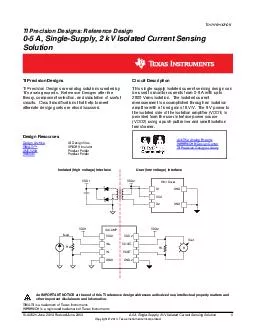
TINA TI is a trademark of Texas Instruments WEBENCH is a registered trademark of Texas Instruments SLAU521 June 2013 Revised June 2013 5A Single Supply 2kV Isolated Current Sensing Solution Copyright 2013 Texas Instruments Incorporated Tom Hendrick ID: 9260

TINA

Share:

Link:

Embed:

Download Presentation from below link

Download Pdf The PPT/PDF document "An IMPORTANT NOTICE at the end of this T..." is the property of its rightful owner. Permission is granted to download and print the materials on this web site for personal, non-commercial use only, and to display it on your personal computer provided you do not modify the materials and that you retain all copyright notices contained in the materials. By downloading content from our website, you accept the terms of this agreement.


Presentation Transcript

An IMPORTANT NOTICE at the end of this TI reference design addresses authorized use, intellectual property matt ers and other important disclaimers and information. TINA - TI is a trademark of Texas Instruments WEBENCH is a registered trademark of Texas Instruments SLAU521 - June 2013 - Revised June 2013 0 - 5A, Single - Supply, 2kV Isolated Current Sensing Solution 1 Copyright © 2013, Texas Instruments Incorporated Tom Hendrick TI Precision Designs : Reference Design 0 - 5 A, Single - Supply, 2 kV Isolated Current Sensing Solution TI Precision Designs Circuit Description TI Precision Designs are analog solutions created by TI’s analog experts. Reference Designs offer the theory, component selection, and simulation of useful circuits. Circuit modifications that help to meet alternate design goals are also discussed. This single supply isolated current sensing design can be used to monitor currents from 0 - 5 A with up to 2500 Vrms isolation. The isolated current measurement is accomplished through an isolation amplifier with a fixed gain of 8 V/V . The 5 V power to the isolated side of the isolation amplifier (VDD1) is provided from the user interface power source (VDD2) using a push - pull driver and small isolation transformer. Design Resources Design Archive All Design files TINA - T I™ SPICE Simulator AMC1200 Product Folder Ask The Analog Experts WEBENCH® Design Center TI Precision Designs Library SN6501 Product Folder www.ti.com 2 0 - 5A, Single - Supply, 2kV Isolated Current Sensing Solution SLAU521 - June 2013 - Revised June 2013 Copyright © 2013, Texas Instruments Incorporated 1 Design Summary The design requirements are as follows :  Generated Isolated Supply Voltage (VDD1) : 5.0 Vdc ( ± 3%)  VDD1 Output Current: 8 mA (max)  Isolated Sense Current: 0 - 5 A  Maximum Shunt Voltage: 250 mV The design goals and performance are summarized in Table 1 . Figure 1 depicts the measured trans ient response of the design. Table 1 : Co mparison of Design Goals and Simulated/ Measured Performance Goal Simulated Offset Voltage ±2 mV - 957.09 µV Current Measurement Error (%FSR) ±0.5% - 0.27% Goal Measured VDD1 Supply Voltage ± 3% +6 - 8% Figure 1 : Simulated Transient Response www.ti.com SLAU521 - June 2013 - Revised June 2013 0 - 5A, Single - Supply, 2kV Isolated Current Sensing Solution 3 Copyright © 2013, Texas Instruments Incorporated 2 Theory of Operation The goals of this design are twofold; the primary goal is to be able to show accurate current measurements from 0 - 5 A from an AC current source. T he second goal is to power the isolated side of the current shunt mo nitor from a 5 V source on the user interface , or output side , of the isolation amplifier. 2.1 Isolated Current Shunt Measurement The current to be sensed on the isolated side of the circuit (Iload) will be fed through a shunt resistor (R sh ). Iload genera tes a voltage across the shunt resistor (V sh ) that is proportional to the value of the shunt resistor. The differential output voltage of the circuit is the product of the amplifier gain (G) and the voltage across the shunt V sh . The AMC1200 output has a fixed common mode voltage based on the VDD2 rail. When V DD2 is equal to 5 V, the output common - mode voltage is 2.55 V. Figure 2 : Isolation Amplifier Topology 2.2 Isolated Power Supply Providing a 5 V high side power supply will be realized using a push - pull driver (the SN6501), a pulse transformer, two rectifiers , and multi - layer ceramic capacitors. Figure 3 depicts the basic transformer circuit which will provide the necessary power to the input side of the isolation amplifier. V DD1 is the ‘hot’ or isolated , side of the circuit while VDD2 is the user supplied 5 V. The transformer used in this design is rated for 2500 Vrms isolation. Figure 3 : Isolation Transformer Topology www.ti.com 4 0 - 5A, Single - Supply, 2kV Isolated Current Sensing Solution SLAU521 - June 2013 - Revised June 2013 Copyright © 2013, Texas Instruments Incorporated The magnitude of V sh is proportional to the amount of current flowing through the shunt resistor, R s h . The maximum V sh voltage the amplifier can see before clipping is ±320 mV. To remain in a linear operating region, the specified maximum differential voltage at the input t o the amplifier is limited to ±250 mV. This is going to be the limiting factor on the size of the shunt resistor. The following equation can be used to calculate the value of R sh : ( 1 ) It is recommended to use the maximum shunt resistance possible to provide the widest dynamic range for the system. Using a larger shunt also has the negative effect of increasing the power dissipation in the sense element. As a general rule, use a sense resistor with a power rating of at least 1.5 times the typical power dissipation expected in the circuit to minimize errors induced by self heating. Power through the resistor (PR sh ) is the product of the current squared and the shunt resistor value as de tailed in equation (2). ( 2 ) The gain in this design is fixed by the isolation amplifier at G=8 and can be evaluated using equation (3). (3 ) www.ti.com SLAU521 - June 2013 - Revised June 2013 0 - 5A, Single - Supply, 2kV Isolated Current Sensing Solution 5 Copyright © 2013, Texas Instruments Incorporated 3 Component Selection 3.1 Isolation Amplifier The AMC1200 was chosen for this application because of its high input bandwidth, the low current drawn on its high - side supply, and its high voltage isolation capability. 3.2 Rectifier Selection The chosen rectifier diode should possess low - forward voltage to provide as much voltage to the converter output as possible. When used in high - frequency switching applications the rectifier must also possess a short recovery time. Schottky diodes meet both of these requirements. The MBR0520L with a typical forward voltage of approxima tely 100 mV at 8 mA forward current was used in this low voltage design. Figure 4 : Forward Voltage of the Rectifier www.ti.com 6 0 - 5A, Single - Supply, 2kV Isolated Current Sensing Solution SLAU521 - June 2013 - Revised June 2013 Copyright © 2013, Texas Instruments Incorporated 3.3 Transformer Selection To ensure that a magnetic core does not saturate , the magnetic s are design ed to dissipate the average stored magnetic flux over each switching cycle of the controller . This is what is known as volt - seconds balance. The average volt - seconds applied to the magnetic s during the switch on time must equal the average volt - seconds acro ss the magnetic s during the off time. To prevent the isolation transformer from saturating, its volt - seconds (V - t) product must be greater than the maximum volt - seconds product applied by the SN6501. The maximum voltage delivered by the SN6501 is the nomi nal converter input plus 10%. The maximum time this voltage is applied to the primary is half the period of the lowest frequency at the specified input voltage. The minimum switching frequency of the SN6501 at 5 V operation is 300 kHz. The refore the trans former’s minimum V - t product, as determined by equations (1) and (2) in the SN6501 data sheet, is 9.1 µ s. When searching for a suitable transformer, it is necessary to determine the minimum turns ratio requi red that will allow the push - pull converter to operate over the specified current and temperature range. This can be expressed through the ratio of secondary to primary voltage multiplied by a correction factor that takes the transformer’s typical efficien cy into account. Equations (3) through (8) in the SN6501 data sheet step through the specific requirements for determining the minimum turns ratio for a given application. For this design, E quation (8) from the SN6501 data sheet (assuming no low drop out regulator is needed) is used as a starting point to determine the minimum turns ratio requirement. The turns ratio determination is based on the following equation assuming a forward voltage of 100mV (Vf) across the rectifier with an 8 mA load, the minim um and maximum voltage requirements for the amplifier as noted in design summary, the transformer correction factor , and drain - source on resistance (R DS on ) noted in the SN6501 datasheet, and maximum current listed in the design summary: ( 4 ) 3.4 Shunt Resistor The shunt resistor which provides 250 mV with a 5 A load was calculated to be 0.05Ω. This is a standard value shunt resistor and is available with a tolerance of 1% and a temperature coefficient as low as ±50ppm/°C. 3.5 Passive Com ponent Selection The capacitors in the converter circuit are multi - layer ceramic chip (MLCC) capacitors. As with all high speed CMOS ICs, the SN6501 requires a bypass capacitor in the range of 10 nF to 100 nF. The input bulk capacitor at the center - tap o f the primary is 10 µ F, which supports the current into the primary during the fast switching transients. On the secondary side of the transformer, a bulk capacitor of 22 µ F will be used at the rectifier outputs. www.ti.com SLAU521 - June 2013 - Revised June 2013 0 - 5A, Single - Supply, 2kV Isolated Current Sensing Solution 7 Copyright © 2013, Texas Instruments Incorporated 4 Simulation The TINA - TI™ schematic shown in Figure 5 includes the circuit values obtained in the design process. Figure 5 : TINA - TI ™ Schematic of the Isolation Amplifier The current source is defined as a sinusoidal current of 5 A at a frequency of 5 kHz. The differential output voltage can be monitored through a standard volt meter or delivered to an analog to digital converter with a differential input. The output voltage range of the AMC1200 is dependent on the applied VDD2. As configured here, the output swing is ±2 V (differential) with a common mode level of 2.55 V. www.ti.com 8 0 - 5A, Single - Supply, 2kV Isolated Current Sensing Solution SLAU521 - June 2013 - Revised June 2013 Copyright © 2013, Texas Instruments Incorporated 4.1 DC Transfer Function The result of the dc transfer function simulation is shown in Figure 6 . Figure 6 : DC Transfer Function Table 2: Output Voltage versus input Current Current (A) Output Voltage - 5 - 1.9960 V 0 - 957.09 µ V +5 1.9936 V 4.2 Frequency Response The AC Transfer Characteristics of the circuit from Figure 5 are shown in Figure 7 . Figure 7 : AC Analysis The bandwidth of the isolation amplifier is 92.98kHz. The dc gain according to the simulation is 18.04dB or 7.97 V/V . www.ti.com SLAU521 - June 2013 - Revised June 2013 0 - 5A, Single - Supply, 2kV Isolated Current Sensing Solution 9 Copyright © 2013, Texas Instruments Incorporated 4.3 Error Analysis A closer analysis of the raw data from figure 6 was used in order to calculate the positive and negative full scale errors as well as the offset of the differential output voltage. At 0A flowing through the load, the differential output voltage was - 957.09µV. For positive full scale current, the output voltage was 1.9936V. For negative full scale current, the output voltag e was - 1.9960. After correcting for the offset voltage, the following equation was used to calculate %FSR. ( 5) The negative full scale error was 0.25%, which also falls within the original design goals. 4.4 VDD1 Error The output voltage from the transformer, used for the VDD1 supply on the isolation amplifier, was measured using SN6501 Multi - Transformer EVM . A single AMC1200 draws only 8 mA max, which hampers the efficiency and regulation capabilities of the power supply. Using the curve found in Figure 8 of the SLLU174 document, the estimated voltage applied to the AMC1200 will be between 5.3 and 5. 4 V . This deviation from 5 V is approximately two times larger than the des ign goal of 5 V +/ - 3%. Measuring directly at the output of the Multi - Transformer EVM, the VDD1 supply was found to be 5.37 V. Simulating the DC Transfer with 5.4 V applied to VDD1 did show an increase in the offset voltage, but the overall current measu rements remained at the 0.27% level. 4.5 Result Summary Table 2 summarizes the simulated and estimated performance of the design. Table 3 : Comparison of Design Goals and Simulated/ Measure d Performance Goal Simulated Offset Voltage ±2mV - 957.09µV Error (%FSR) ±0.5% - 0.27% Goal Measured VDD1 Supply Voltage 5 V 5.37 V 5 Modifications The components selected for this design were based on the design goals outlined at the beginning of the design process. Introducing an LDO at the output of the transformer will provide a more stabile VDD1 rail, but this comes at the additional costs associ ated with board space, component count, and perhaps a different transformer depending on the number of current sensing channels needed in the design. www.ti.com 10 0 - 5A, Single - Supply, 2kV Isolated Current Sensing Solution SLAU521 - June 2013 - Revised June 2013 Copyright © 2013, Texas Instruments Incorporated Adding an LDO to the secondary side of the transformer would require the circuit designer to account for the minimum voltage needed at the LDO input to maintain the desired output voltage. Using the TPS76350 as an example, the regulator needs 75 mV (max) of headroom to maintain 5.0 V out with a 50 mA load. This would provide enough power to drive up to five AMC1200 devices. A second potential modification to this design would be to replace the 5 V VDD2 source with a 3.3 V supply. With a slightly larger turns ratio on the transformer, the 5 V necessary for the VDD1 rail on the AMC1200 could be realized (with or without an LDO). This would provide a ±2 V differential output voltage from the AMC1200 centered at 1.29 V. 6 Acknowledgements & References 1. SN6501 Multi - Transformer EVM Users Guide (SLLU174) IMPORTANTNOTICE TexasInstrumentsIncorporatedanditssubsidiaries(TI)reservetherighttomakecorrections,enhancements,improvementsandother changestoitssemiconductorproductsandservicesperJESD46,latestissue,andtodiscontinueanyproductorserviceperJESD48,latest issue.Buyersshouldobtainthelatestrelevantinformationbeforeplacingordersandshouldverifythatsuchinformationiscurrentand complete.Allsemiconductorproducts(alsoreferredtohereinas“components”)aresoldsubjecttoTI’stermsandconditionsofsale suppliedatthetimeoforderacknowledgment. TIwarrantsperformanceofitscomponentstothespecificationsapplicableatthetimeofsale,inaccordancewiththewarrantyinTI’sterms andconditionsofsaleofsemiconductorproducts.TestingandotherqualitycontroltechniquesareusedtotheextentTIdeemsnecessary tosupportthiswarranty.Exceptwheremandatedbyapplicablelaw,testingofallparametersofeachcomponentisnotnecessarily performed. TIassumesnoliabilityforapplicationsassistanceorthedesignofBuyers’products.Buyersareresponsiblefortheirproductsand applicationsusingTIcomponents.TominimizetherisksassociatedwithBuyers’productsandapplications,Buyersshouldprovide adequatedesignandoperatingsafeguards. TIdoesnotwarrantorrepresentthatanylicense,eitherexpressorimplied,isgrantedunderanypatentright,copyright,maskworkright,or otherintellectualpropertyrightrelatingtoanycombination,machine,orprocessinwhichTIcomponentsorservicesareused.Information publishedbyTIregardingthird-partyproductsorservicesdoesnotconstitutealicensetousesuchproductsorservicesorawarrantyor endorsementthereof.Useofsuchinformationmayrequirealicensefromathirdpartyunderthepatentsorotherintellectualpropertyofthe thirdparty,oralicensefromTIunderthepatentsorotherintellectualpropertyofTI. ReproductionofsignificantportionsofTIinformationinTIdatabooksordatasheetsispermissibleonlyifreproductioniswithoutalteration andisaccompaniedbyallassociatedwarranties,conditions,limitations,andnotices.TIisnotresponsibleorliableforsuchaltered documentation.Informationofthirdpartiesmaybesubjecttoadditionalrestrictions. ResaleofTIcomponentsorserviceswithstatementsdifferentfromorbeyondtheparametersstatedbyTIforthatcomponentorservice voidsallexpressandanyimpliedwarrantiesfortheassociatedTIcomponentorserviceandisanunfairanddeceptivebusinesspractice. TIisnotresponsibleorliableforanysuchstatements. Buyeracknowledgesandagreesthatitissolelyresponsibleforcompliancewithalllegal,regulatoryandsafety-relatedrequirements concerningitsproducts,andanyuseofTIcomponentsinitsapplications,notwithstandinganyapplications-relatedinformationorsupport thatmaybeprovidedbyTI.Buyerrepresentsandagreesthatithasallthenecessaryexpertisetocreateandimplementsafeguardswhich anticipatedangerousconsequencesoffailures,monitorfailuresandtheirconsequences,lessenthelikelihoodoffailuresthatmightcause harmandtakeappropriateremedialactions.BuyerwillfullyindemnifyTIanditsrepresentativesagainstanydamagesarisingoutoftheuse ofanyTIcomponentsinsafety-criticalapplications. Insomecases,TIcomponentsmaybepromotedspecificallytofacilitatesafety-relatedapplications.Withsuchcomponents,TI’sgoalisto helpenablecustomerstodesignandcreatetheirownend-productsolutionsthatmeetapplicablefunctionalsafetystandardsand requirements.Nonetheless,suchcomponentsaresubjecttotheseterms. NoTIcomponentsareauthorizedforuseinFDAClassIII(orsimilarlife-criticalmedicalequipment)unlessauthorizedofficersoftheparties haveexecutedaspecialagreementspecificallygoverningsuchuse. OnlythoseTIcomponentswhichTIhasspecificallydesignatedasmilitarygradeor“enhancedplastic”aredesignedandintendedforusein military/aerospaceapplicationsorenvironments.BuyeracknowledgesandagreesthatanymilitaryoraerospaceuseofTIcomponents whichhavenotbeensodesignatedissolelyattheBuyer'srisk,andthatBuyerissolelyresponsibleforcompliancewithalllegaland regulatoryrequirementsinconnectionwithsuchuse. TIhasspecificallydesignatedcertaincomponentsasmeetingISO/TS16949requirements,mainlyforautomotiveuse.Inanycaseofuseof non-designatedproducts,TIwillnotberesponsibleforanyfailuretomeetISO/TS16949. Products Applications Audio www.ti.com/audio AutomotiveandTransportation www.ti.com/automotive Amplifiers amplifier.ti.com CommunicationsandTelecom www.ti.com/communications DataConverters dataconverter.ti.com ComputersandPeripherals www.ti.com/computers DLP®Products www.dlp.com ConsumerElectronics www.ti.com/consumer-apps DSP dsp.ti.com EnergyandLighting www.ti.com/energy ClocksandTimers www.ti.com/clocks Industrial www.ti.com/industrial Interface interface.ti.com Medical www.ti.com/medical Logic logic.ti.com Security www.ti.com/security PowerMgmt power.ti.com Space,AvionicsandDefense www.ti.com/space-avionics-defense Microcontrollers microcontroller.ti.com VideoandImaging www.ti.com/video RFID www.ti-rfid.com OMAPApplicationsProcessors www.ti.com/omap TIE2ECommunity e2e.ti.com WirelessConnectivity www.ti.com/wirelessconnectivity MailingAddress:TexasInstruments,PostOfficeBox655303,Dallas,Texas75265 Copyright©2013,TexasInstrumentsIncorporated