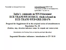
WP29 document ECETRANSWP29201621 which is based on ECETRANSWP29GRE201537e Proposal for Supplement 18 to the original series of amendments to Regulation No 50 ID: 679339
Download Presentation The PPT/PDF document "India’s comments on" is the property of its rightful owner. Permission is granted to download and print the materials on this web site for personal, non-commercial use only, and to display it on your personal computer provided you do not modify the materials and that you retain all copyright notices contained in the materials. By downloading content from our website, you accept the terms of this agreement.
Slide1
India’s comments on WP.29 document ECE/TRANS/WP.29/2016/21, which is based on ECE-TRANS-WP29-GRE-2015-37e Proposal for Supplement 18 to the original series of amendments to Regulation No. 50 (Position, stop, direction indicators lamps for mopeds and motorcycles) (Submitted by the Working Party on Lighting and Light-Signalling)Sequential Direction indicators introduction in UN R 50
Transmitted by the expert from India
Informal
Document
GRE-76-05
(76th session of GRE,
25–28
October 2016
,
agenda items 7 (d) and 10) Slide2
BackgroundWith technological developments in lighting, new designs of direction indicators with sequential activation are regulated in UN regulations. Certification provisions for sequential direction indicators in motor vehicles already exist in 4W UN Regulation 6.Similar provisions of sequential direction indicators in UN R 50 &
UN R 53 were
adopted by GRE
in its 74
th
session held in October 2015 (
ECE-TRANS-WP29-GRE-2015-37e)
and further considered in WP29 session in March 2016 vide documents ECE/TRANS/WP.29/2016/21
.
India wishes to submit following amendments
ECE/TRANS/WP.29/2016/21 Slide3
India’s comment on WP.29 document ECE/TRANS/WP.29/2016/21 (India’s proposed changes are marked in strikethrough for deletions and yellow highlighted text for additions) Paragraph 2.2., insert a new item (c), to read: "2.2. … (c) The sequential activation of light sources, if any. … " Insert a new paragraph 6.8., to read: "6.8. For direction indicator lamps of categories 11, 11a, 11b, 11c or 12 the flash may be produced by
sequential
activation of their light sources if the following conditions are
met
:
(
a
) Each
light source, after its activation, shall remain lit until the end of the ON cycle;
(
b
)
The sequence of activation of the light sources shall proceed in a uniform progressive
manner
from inboard towards the outboard edge of the apparent surface;
(
c
)
It shall be one continuous line without repeat alternation in the vertical direction (e.g.
no
waves);
(
d
) The
variation shall finish no more than 200
ms
after the beginning of the ON cycle;
(
e)
For
the orthogonal projection in the direction of the axis of reference of a rectangle,
circumscribing
the apparent surface of the direction indicator shall have its longer
sides
parallel to
the
H-plane, the ratio of the horizontal to the vertical sides shall not
be
less than 1.7.
Compliance
with the conditions mentioned above shall be verified in flashing mode
.
“
Note
:
For
photometric measurement,
a
flashing mode means a
phase where
all the light sources of
a
sequential direction indicator are activated and remain continuously ON during photometric measurements.”
Annex
2, item 9.,
amend to read:
"9.
Concise
description:3
…
Stop
lamp: yes/ no 2
Sequential
activation of light sources (see paragraph 6.8. of this Regulation): yes/no 2 " Slide4
Justification for Deletion of condition (e) of ECE/TRANS/WP.29/2016/21 (1/2) Conditions (a) to (e) in document ECE/TRANS/WP.29/2016/21 are taken from Para 5.6 of UN R6. Apart of conditions (a) to (d), compliance to condition (e) is also possible in case of 4 wheelers because of their larger widths and space available at front and rear. (especially a ratio of 1.7 for a direction indicator apparent surface orthogonal projection rectangle sides (horizontal side / Vertical side = L/H ratio)
However, this condition (e) is difficult to comply-with in case of two wheelers due to the following reasons:
Two wheelers body widths, where direction indicators are generally mounted, are about 390mm-480mm at front and 320 mm-370 mm at rear
(see examples in slide )
ECE R53 mandates minimum separation distance between inner edges of illuminating surfaces as 240mm for front direction indicators and 180mm for rear direction indicators.
This leaves
only about
75mm-120mm for front indicator and 70mm–95mm for rear indicator as available space on each side (LH & RH) for designing / placing direction indicators. This is especially the case for vehicles like scooters and motorcycles with fairing, wherein many designs of the direction indicators are packaged as part of the body panels/fairing elements.In such cases, in order to differentiate one product from another, and/or to make progression on design and layout, the designer would want to make direction indicators with differing sizes and shapes of apparent surfaces including their orientation of length and widths.The requirement as in condition (e) of ECE/TRANS/WP.29/ 2016/21 takes away such freedom and would be restrictive in design expressions and options.Slide5
The intent of an approaching / preceding vehicle to turn either to the right or left is recognised by the driver/rider of any other vehicle by recognising on which side of the vehicle w.r.t. its Longitudinal Median Plane -(LMP) a direction indicator is flashing.Such a recognition on which side of the vehicle a direction indicator is flashing is also aided by recognising the same w.r.t. vehicle features like headlamp or tail lamp which are normally mounted on LMP.Once the side of the flashing is recognised as above, both regular flash activation and sequential flash activation, get recognised equally correctly.In regular blinkers, there is no length to height ratio requirements in the regulations. In order to demonstrate the above, comparative flashing of sequential direction indicators with L/H ratio < 1 and ratio=1.7 can be seen in this video.
It can be observed from video that, the recognition of the intended direction to turn right or left is not diluted in any way by the sequential activation with a configuration (L/H ratio <1) shown in left side in this video.
From the above it is clear that, in both the above configurations the intended direction is recognised equally and correctly.
In view of the above,
it is proposed that condition (e)
may be deleted from clause 6.8 of this document in UN
R50
.
Also for better clarity
, explanatory note is proposed under Para 6.8 for ‘flashing mode condition’ during photometric measurement.
Justification for Deletion of condition (e) of ECE/TRANS/WP.29/2016/21 (2/2)
L/H < 1
L/H = 1.7
LMP
HL
HL
LMP
LMP
L/H = 1.7
L/H < 1
Video
image:
This video will be presented during GRE
session.Slide6
FrontViewRear View Justification for Deletion of condition (e) of ECE/TRANS/WP.29/2016/21Slide7
Thank You