PDF-Operation Manual
Author : giovanna-bartolotta | Published Date : 2016-11-20
DS2 4 00 Q Q AM Analyzer Ver xFF1A 1 0
Presentation Embed Code
Download Presentation
Download Presentation The PPT/PDF document "Operation Manual" is the property of its rightful owner. Permission is granted to download and print the materials on this website for personal, non-commercial use only, and to display it on your personal computer provided you do not modify the materials and that you retain all copyright notices contained in the materials. By downloading content from our website, you accept the terms of this agreement.
Operation Manual: Transcript
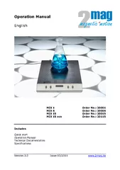
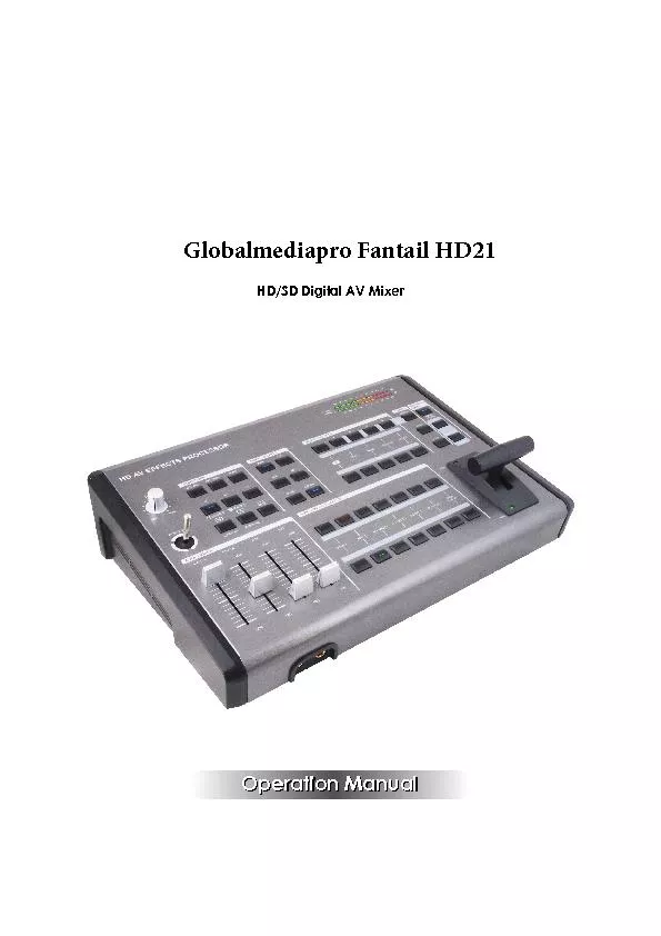
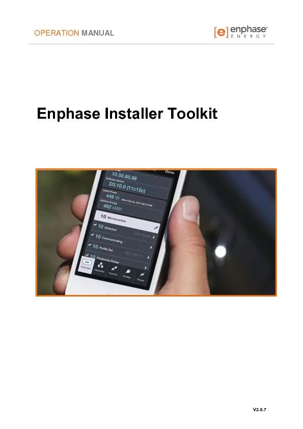
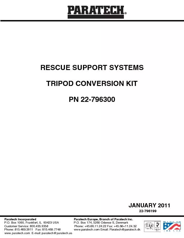
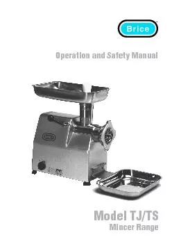
DS2 4 00 Q Q AM Analyzer Ver xFF1A 1 0. 17 DISINTEGRATION TESTER brPage 2br STRUCTURE SPECIFICATIONS Model 17 Speed rpm 540 rpm Stroke 55mm Motor 6W Voltage AC 220V 50 60 Hz Heater 600W Dimension mm W470 x D325 x H555 Weight kgs 22 Puller Beaker Basket Heater Temp Controller Speed Knob Operation Manual English MIX 1 Order No.: 30001 MIX 6 Order No.: 30006 MIX 15 Order No.: 30015 MIX 15 eco Order No.: 30115 Includes Quick start Technical Documentation Specifications Version 3.0 Issue Operation ManualHD/SD Digital AV Mixer CONTENTS 1. INTRODUCTION ....................................................................... 1 2. FEATURES ................................................. Operation ManualHD/SD Digital AV Mixer By:. Eid. . Hamdan. An Najah National University. Department of mechanical Engineering. (Grafting Robot). Supervisor: . Dr.majdi abu qari3. What is grafting??. Its an operation that connect two different parts of plants to gather by specific tool.. OPERATION MANUAL V2.0.7 Enphase Installer Toolkit Operation Manual 2015 Enphase Energy Inc. V2.0.7 2 Contact Information Enphase Energy Inc. 1420 N. McDowell Blvd. Petaluma, CA 94954 http:// Operation Manual Version 1.3 Dave Smith Instruments 1210 Cabrillo Hwy N Half Moon Bay, CA 94019-1449 SIGNATURE ON FILE Change Record Change No. Date Title or Brief Description Signature of Validating Officer 1 17 JAN 2011 Tripod head was modified changed illustrations to reflect the change SIGNAT Operation and Safety Manual Operation and Safety Manual Model TJ/TS Mincer Model TJ/TS Mincer The �rice Model TJ/TS Mincer The Model TJ/TS Mincer range is built for high volumes and hard work. Date: 11 / 08 / 1 2 Revision: 5 This manual covers: PPS Series Programmable DC Power Supplies !. To the Owner/Operator/Dealer. All implements with moving parts are potentially hazardous. There is no substitute for a cautious, safe-minded . operator who . recognizes the potential hazards and follows reasonable safety . provides this manual for the guidance of all owners, operators and servicing personnel in order to obtain the longest possible trouble-free service. It contains data, specifications, warranty, schema WICE-SPI Hardware Operation Manual Contents WICE-SPI Hardware Operation Manual 1.WICE-SPI processes data transmission, programming or emulation through USB 2.0 interface and needs no external power.2. Micro USB CableMount Adapter1 G6 Plus OverviewAccessoriesIntroduction of Interface and screwsIntroduction of Display and BottonsIntroduction of Axis and KnobIntroduction of Other ComponentsAdapterO
Download Document
Here is the link to download the presentation.
"Operation Manual"The content belongs to its owner. You may download and print it for personal use, without modification, and keep all copyright notices. By downloading, you agree to these terms.
Related Documents