/
Directional x-ray radiation Directional x-ray radiation

Directional x-ray radiation - PowerPoint Presentation

jalin
jalin . @jalin
Follow
27 views
Uploaded On 2024-02-03

Directional x-ray radiation - PPT Presentation

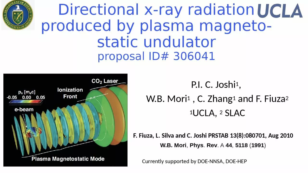
produced by plasma magnetostatic undulator proposal ID 306041 PI C Joshi 1 WB Mori 1 C Zhang 1 and F Fiuza 2 1 UCLA 2 SLAC F Fiuza L Silva and C Joshi PRSTAB ID: 1044286

mode laser pulse beam laser mode beam pulse ionization co2 plasma front static mev electron 100 magneto produced 266

Share:

Link:

Embed:

Download Presentation from below link

Download Presentation The PPT/PDF document "Directional x-ray radiation" is the property of its rightful owner. Permission is granted to download and print the materials on this web site for personal, non-commercial use only, and to display it on your personal computer provided you do not modify the materials and that you retain all copyright notices contained in the materials. By downloading content from our website, you accept the terms of this agreement.


Presentation Transcript

1. Directional x-ray radiation produced by plasma magneto-static undulatorproposal ID# 306041P.I. C. Joshi1, W.B. Mori1 , C. Zhang1 and F. Fiuza21UCLA, 2 SLACF. Fiuza, L. Silva and C. Joshi PRSTAB 13(8):080701, Aug 2010W.B. Mori, Phys. Rev. A 44, 5118 (1991)Currently supported by DOE-NNSA, DOE-HEP

2. What is a plasma magneto-static (MS)modeThe two normal electrostatic modes (collective waves) in an unmagnetized plasma are Bohm Gross Waves or electron plasma waves and ion acoustic waves.Unmagnetized plasma can support another mode. It has zero frequency but a spatially periodic magnetic field –magneto-static (MS) mode.How is it produced? it is produced by a periodic excitation of dc currents in the plasma.This mode has hitherto not been observed.There is a connection between this mode and the filamentation/Weibel instability produced magnetic field (see Chaojie Zhang’s proposal)

3. What happens when e.m. wave is incident on a relativistic underdense plasma ionization front?Ionization front   Incident wave and 2 >  Ionization front f=  Boundary conditions at the ionization front are E and B must be continuous and J=0 since electrons are born at rest3 boundary conditions allows for 3 modesTransmitted Wave Reflected Wave Magneto-static mode  Free Space Containing GasDrive Laser  Ref: F. Fiuza, L. Silva and C. Joshi PRSTAB 13(8):080701, Aug 2010

4. Physical Mechanism behind MS modeIonization front must be narrower than ½ wavelength of CO2 radiation½ m vosc2 = 1.5 kV for CO2 RelativisticW.B. Mori, Phys. Rev. A 44, 5118 (1991)

5. How is the magneto static mode produced?1) An ultrashort 0.266 um (drive)laser pulse containing ~10 mJ of energy in a 50 fs pulse generates in a hydrogen gas cell a propagating ionization front (f) with density >1019 cm-32) A counter propagating 2 ps duration CO2 (incident)laser pulse with a peak intensity of 1x10¹³ W/cm2 (below the ionization threshold of H2) collides with the ionization front.The time dependent refractive index front reflects and and transmits the CO2 laser pulse and frequency upshifts it.At the same time a static magnetic field is left behind in the plasma that can reach very high B.

6. Intensity Contours and Ionization fraction with 266nm 5mJ, 40fs pulse90% in 11 fs266 nm, 40fsIdeally we want It should at least be half the CO2 period = 16 fs 

7. Concept that gives rise to MS modeCO2 Laser pulse  IonizingLaser  MS Mode50 MeV electron BeamWait for the CO2 laser pulse to pass before sending the electronBeam through the static magnetic undulator left behind.

8. Example of Spontaneous emission produced by 5 MeV beam nb=8x1016 cm-3, passing through 5x1020 cm-3density plasma MS mode undulatorInitial BFinal B1D OSIRIS

9. How can such an experiment be done?ATF has recently added a Ti Sapphire laser to their CO2 laser and nominally 50 MeV electron beamTi-sapphire 80 mJ min. at IP in 75 fs (FWHM)They should be able to get >20 mJ in 50 fs at 0.4 um or 10 mJ at 0.266 um.E-beam 50 MeV, 10s pC in 100-200 fsCO2 laser 200 mJ in 2 ps at IPNeed 0.4 um and e-beam to be collinear while CO2 laser to be counter propagating. Gas target 2 mm long He/H gas jet.

10. What do we want to do?(h Here = 0.12 eVFor =100, h We can see these in a single photon counting mode. Average power 10 W or number of photons 104Cone angle 1/ or 10 mrad.The spectral width narrows to 1/N where N are the number of undulator periods. For instance for a 1mm long undulator This is measurable using an X-ray CCD operating in the single photon counting mode. 

11. Why ATF for this experiment?Only place in the word that has (or will have) a 5-75 MeV electron beam, a TW class CO2 laser and a TW class Ti-sapphire laser under one roofAll three are synchronize w.r.t. one another with ~100fs accuracyATF has a mandate to explore novel sources of radiation

12. What is needed from ATF?The 800nm Ti -sapph laser pulse needs to be frequency trippled without bandwidth narrowing (thin crystals) to give > 5mJ at 266 nm.The CO2 and the 266 nm laser pulses are counter propagating and meet at the center of the target chamber, that has a 2-3 mm H gas jetThe 100 fs e-beam and the 266 nm pulse are colinear. The e-beam follows the 266nm pulse with a 50-several hundred fs delay (probably need two delay lines for the laser pulses).Need 2-3 years with 2 weeks of running time and 3 days of set-up time every year.

13. What will the experimenters provideX-ray CCD for detecting the forward emitted few KV X-raysA very high density H gas get. IR spectrometer to measure the frequency upshifted transmitted CO2 photons.A small dipole magnet to dump the incident electrons.An output flange for the radiated photons with an 500 um thick 2” Be window. This will be followed by the X-ray CCD.Miscellaneous optics and manpower (postdoc and a graduate student)

14. What will be regarded as a success?Conclusive observation of X-rays of expected energy Observation of X-rays contingent upon all the null tests being successful: No CO2, no electron beam, No ionization front no X-raysDetermination of the lifetime of the MS mode, its dependence on plasma density, ionization front width etc.Future work: control the phase velocity of the ionization front by using a spatially chirped pulse and spatially dispersive optic (flying focus), overdense plasma to increase the yield, increase the B field to 100 T.

15. Summary Laser technology has now progressed sufficiently so that a magneto static mode can be excited in a plasma using a relativistic ionization front for the first time (future text book entry)This mode will act as a extremely small period but highly accurate undulator for a relativistic electron beam.Because of a large number of periods, it will produce a spectrally narrow beam of photons in the direction of the electrons.At ATF this concept can be tested as a precursor to attempting gain in the uv .This experiment will also provide a known periodic B field for probing by an orthogonal e-beam (see Chaojie’s talk).

16. Intensity Contours and Ionization fraction with 800 nm 80 mJ, 75 fs pulseLinearly polarized, 75 ps pulses to give peakIntensity of 4x10¹⁵ W/cm2PPT theory (Courtsey Noa Nambu)90% in 20 fs800 nm

17. ParameterUnitsTypical ValuesCommentsRequested ValuesBeam EnergyMeV50-65Full range is ~15-75 MeV with highest beam quality at nominal values50Bunch ChargenC0.1-2.0Bunch length & emittance vary with chargeLarger the better but >100pCCompressionfsDown to 100 fs (up to 1 kA peak current)A magnetic bunch compressor available to compress bunch down to ~100 fs. Beam quality is variable depending on charge and amount of compression required. NOTE: Further compression options are being developed to provide bunch lengths down to the ~10 fs level200FsTransverse size at IP (s)mm30 – 100 (dependent on IP position)It is possible to achieve transverse sizes below 10 um with special permanent magnet optics.20-100umNormalized Emittancemm1 (at 0.3 nC)Variable with bunch chargefineRep. Rate (Hz)Hz1.53 Hz also available if needed Trains mode---Single bunchMulti-bunch mode available. Trains of 24 or 48 ns spaced bunches.Electron Beam Requirements

18. ConfigurationParameterUnitsTypical ValuesCommentsRequested ValuesCO2 Regenerative Amplifier BeamWavelengthmm9.2Wavelength determined by mixed isotope gain mediaPeak PowerGW~3Pulse Mode---SinglePulse Lengthps2Pulse EnergymJ6M2---~1.5Repetition RateHz1.53 Hz also available if neededPolarization---LinearCircular polarization available at slightly reduced powerHigh rep rate for setting upCO2 CPA BeamWavelengthmm9.2Wavelength determined by mixed isotope gain mediaNote that delivery of full power pulses to the Experimental Hall is presently limited to Beamline #1 only.Peak PowerTW2~5 TW operation is planned for FY21 (requires further in-vacuum transport upgrade). A 3-year development effort to achieve >10 TW and deliver to users is in progress.Pulse Mode---SinglePulse Lengthps2Pulse EnergyJ~5Maximum pulse energies of >10 J will become available in FY20200mJM2---~2Repetition RateHz0.05PolarizationLinearAdjustable linear polarization along with circular polarization will become available in FY20CO2 Laser Requirements

19. Ti:Sapphire Laser SystemUnitsStage I ValuesStage II ValuesCommentsRequested ValuesCentral Wavelengthnm800800Stage I parameters should be achieved by mid-2020, while Stage II parameters are planned for late-2020.266 nmFWHM Bandwidthnm2013Compressed FWHM Pulse Widthfs<50<75Transport of compressed pulses will initially include a very limited number of experimental interaction points. Please consult with the ATF Team if you need this capability.As short as possible50 fsChirped FWHM Pulse Widthps5050Chirped EnergymJ10200Compressed EnergymJ7100Energy to ExperimentsmJ>4.9>805-10mJPower to ExperimentsGW>98>1067Other Experimental Laser RequirementsNd:YAG Laser SystemUnitsTypical ValuesCommentsRequested ValuesWavelengthnm1064Single pulseEnergymJ5Pulse Widthps14Wavelengthnm532Frequency doubledEnergymJ0.5Pulse Widthps10

20. Longer range plan: A possible SASE FEL action with 10 MeV beam