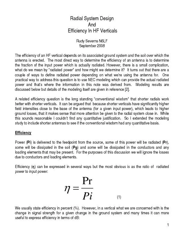
/
90% that represents a signal loss of about -0.46 dB if the efficiency 90% that represents a signal loss of about -0.46 dB if the efficiency

90% that represents a signal loss of about -0.46 dB if the efficiency - PDF document

jane-oiler
jane-oiler . @jane-oiler
Follow
376 views
Uploaded On 2016-07-18

90% that represents a signal loss of about -0.46 dB if the efficiency - PPT Presentation

log10 2 Radiated power Pr Our definition of efficiency is a direct function of The meaning of input power is obvious is to compute the total power passing through a virtual surface comple ID: 409143

log10 (2) Radiated power

Share:

Link:

Embed:

Download Presentation from below link

Download Pdf The PPT/PDF document "90% that represents a signal loss of abo..." is the property of its rightful owner. Permission is granted to download and print the materials on this web site for personal, non-commercial use only, and to display it on your personal computer provided you do not modify the materials and that you retain all copyright notices contained in the materials. By downloading content from our website, you accept the terms of this agreement.


Presentation Transcript

log10 (2) 90% that represents a signal loss of about -0.46 dB if the efficiency is only 60% then the signal loss will use, although for some graphs Radiated power (Pr) Our definition of efficiency is a direct function of . The meaning of "input power" is obvious is to compute the total power passing through a virtual surface completely enclosing the antenna. For the absence of ground losse everywhere in space and the choice of e value for r does matter. skywave propagation for DX then you will be intereradiated into space. Ground loss This is the average represents the fraction of the input power which is radiated at an infinite distance, i.e. GaPiPr (3) Dividing through by == (4) EZNEC gives in two forms, a decimal varfect ground no power is lost and lently, 0 dB. Over real ground still represents the radiated power but B value which takes 2 into account the power dissipated in the ground surface out to infinity. The curvature of the earth is not taken into account in the NEC common to think of efficiency in terms of only the near-field losses wi. For that reason when calculating the radius of the hemisphere is typically made 1/2 to 1 wavelength and intediated power density go on to determine The problem with this approach is that NEC does not automatically do this for you. You have to first use NEC to compute the complex values of the ace of the hemisphere skill. Taking this approach you will get values for which reflect what is This information may be interesting but if your only interest is in determining the improvement in your provide, then you can just use the average gain calculation. No math skills required! The incremental change in signal will be very similar for both methods but the absolute values for 7.2 MHz Modeling results Figures 1 and 2 show the efficiency for = 1 wavelength for two different soils. -5.00-4.50-4.00-3.50-3.00-2.50-2.00-1.50-1.00-0.500.10.150.20.250.30.350.40.450.5Radial length [wavelengths]Efficiency [dB] 4 radials 7.2 MHz0.005/13 soilr=40m 16 radials 32 radials 64 radials 8 radials 128 radials 3 Figure 1, efficiency in dB as a function of radial number and length in average soil. r=40 m. -2.5-1.5-0.50.10.150.20.250.30.350.40.450.5Radial length [wavelengths]Efficiency [dB] 4 radials 7.2 MHz 16 radials 32 radials 64 radials 8 radials 128 radials =40 m. These two figures very clearly illuverage ground) we see something funny. When using only four radials, as we increase the length from 1/8-wave the efficiency goes down, not up. The same thing happens for eight radials only not quite as much. More copper re 2 which is for the same antenna over very good ground. In this harm but also does little soils are a waste of copper. The loss effect seen in figure 1 stems increase ground loss. This effect Alternately we can graph efficiency in terms of Ga as shown in figures 3 and 4. Unfortunately this the efficiency of a 1/4-wave vertical is still only -2.76 dB (53%)! 4 0.100.150.200.250.300.350.400.450.50Radial length [wavelengths] 128 radials 64 radials 32 radials 16 radials 8 radials 4 radials 7.2 MHz0.005/13 soilr=infinity Ga 0.100.150.200.250.300.350.400.450.50Radial length [wavelengths]Average gain [dB] 128 radials 64 radials 32 radials 16 radials 8 radials 4 radials 7.2 MHz0.02/30 soilr=infinity Figure 4, Efficiency in terms of Ga for very good soil. This observation does not imply we should abandon verticals! In many cases, particularly on is usually limited, verticals can ofthe desired low angles for DXing than a practical horizontal antenna. Incorporated into arrays verticals provide a practical way to have gain 5 phs for verticals over seawater we would see the efficiency become very nearly 0 dB and essentially ind why verticals can work so well for some DXpeditions. 1.8 MHZ modeling with a 1/4-wave vertical I also1/4-wave and 1/8-wave verticals at 1.8 MHz over average soil to between height is has been changed from efficiency in dB to "improvement in dB" when going s to more and/or longer radials. The gain for four 1/8-wave radials was used as the reference and set to 0 dB. I did this because it nicely illustrates what you "gain" by adding more cop How tters. As we can see from graph when only a few radials are used, making them longer is waste. Yoof wire, as substantial ground system. 0.10.150.20.250.30.350.40.450.5Radial length [wavelengths]Improvement [dB] 4 radials f=1.8 MHz0.005/13 soilh=1/8-wave 8 radials 16 radials 32 radials 64 radials 128 radials 2 wl 4 wl 8 wl 16 wl 1 wl Figure 5, improvement in dB for various radial combinations for a 1/8-wave vertical. 6 0.10.150.20.250.30.350.40.450.5Radial length [wavelengths] 4 radials f=1.8 MHz0.005/13 soilh=1/4-wave 8 radials 16 radials 32 radials 64 radials 128 radials 2 wl 4 wl 8 wl 16 wl 1 wl Figure 6, improvement in dB for various radial combinations for a 1/4-wave vertical. Referring to figure 5, which is for an 1/8-wave vertical. If your wire length is limited to four wavelengths, you are much better off to use thiruse either thirty two 1/4-wave or sixty four 1/8-wave radials. The choice becomes one of convenience in laying out 1/4-wave radials then the radials will work just as well. When you go up to 16 wavelengths of wire then sixty four 1/4-wave radials work best. When we look at the gain improvement shown in figure 6, which is for a 1/4-wave vertical, we see similar behavior except that when we are using 8 wavelengths of wire there is a clear advantage to go from 1/8-wave to 1/4-wave radialvelengths of wire then radial lengths of 3/8-wavelength are best. length as the height of the vertical element". In nd this, longer radials are more 4-wave vertical (figure 6), for small amounts of wire 1/8-wave radials are best but as we make more wire available the 1/4-wave radials are superior. The physics of this e base of the antenna, adding more close in copper doesn't buy much. 7 8 In both cases it wouluntil we go to 16 or more wavelengths of wire. Summary The choice of what constitutes usefll "the efficiency". In the typical case where we are interested in the power radiated into space for DX communications, efficiencies are typically quite low, except perhaps over seawater. dB). This is intrinsic to vertical polarization agation in the far-field. This does not to imply that horizontally polarized antennas are always superior to verticals! applications where a verticr DX or ground wave work than a in frequency towards 160m. References [1] Severns, Rudy, N6LF, Antenna Ground Systemwww.antennasbyn6lf.Com . [2] Severns, Rudy, N6LF, Radiation Resistance Vaystem Design, September