/
DETERMINATION OF BOUNDARIES, GEOLOGICAL OUTCROPS AND STRUCTURAL FEATUR DETERMINATION OF BOUNDARIES, GEOLOGICAL OUTCROPS AND STRUCTURAL FEATUR

DETERMINATION OF BOUNDARIES, GEOLOGICAL OUTCROPS AND STRUCTURAL FEATUR - PDF document

jane-oiler
jane-oiler . @jane-oiler
Follow
397 views
Uploaded On 2017-02-28

DETERMINATION OF BOUNDARIES, GEOLOGICAL OUTCROPS AND STRUCTURAL FEATUR - PPT Presentation

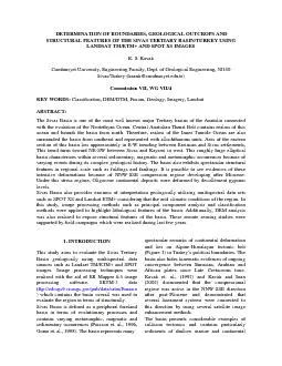
ftpedcsgs9crusgsgovpubdatasrtmEurasia which contains the basin overall was used to evaluate the region in terms of structurally Sivas Basin is defined as a peripheral foreland basin in te ID: 520422

ftp://edcsgs9.cr.usgs.gov/pub/data/srtm/Eurasia) which contains the basin

Share:

Link:

Embed:

Download Presentation from below link

Download Pdf The PPT/PDF document "DETERMINATION OF BOUNDARIES, GEOLOGICAL ..." is the property of its rightful owner. Permission is granted to download and print the materials on this web site for personal, non-commercial use only, and to display it on your personal computer provided you do not modify the materials and that you retain all copyright notices contained in the materials. By downloading content from our website, you accept the terms of this agreement.


Presentation Transcript

DETERMINATION OF BOUNDARIES, GEOLOGICAL OUTCROPS AND STRUCTURAL FEATURES OF THE SIVAS TERTIARY BASIN/TURKEY USING LANDSAT TM/ETM+ AND SPOT XS IMAGES K. S. Kavak Cumhuriyet University, Engineering Faculty, Dept. of Geological Engineering, 58140 Sivas/Turkey-(kaank@cumhuriyet.edu.tr) Commission VII, WG VII/4 KEY WORDS: Classification, DEM/DTM, Fusion, Geology, Imagery, Landsat BSTRACT: The Sivas B ftp://edcsgs9.cr.usgs.gov/pub/data/srtm/Eurasia) which contains the basin overall was used to evaluate the region in terms of structurally. Sivas Basin is defined as a peripheral foreland basin in terms of evolutionary pr environment starting from Upper Paleocene-Eocene. 2. GEOLOGIC SETTING Sivas Basin is surrounded several litospheric fragments and suture zones (Figure 1). First of all, Central Anatolian Thrust Belt (Tatar, 1982) is located on the northern margin of the basin and represents as a suture zone on the northern branch of Neotethyan Ocean which was also known Izmir-Ankara Zone (Brinkmann, 1976). This collisional process was realized on the southern margin of the Eurasian plate and the Apulo-Anatolian block in regional scale (Poisson et. al., 1996). Kirsehir Massif is formed roughly continental basement of the basin (Gorur et. al., 1984). The massif is located in Anatolides-Taurides, as one of the main tectonic units of Turkey (Ketin, 1966). This fragment was composed of mainly metamorphic occurrences and intrusives. On the other hand, Inner Tauride Suture separates Munzur and Bitlis prolongations and bounds the basin from south (Sengor and Yilmaz, 1981). This suture also determines southern branch of the Neotethyan ocean. BLACK SEAMEDITERRANEAN SEA0 km 20AnkaraSivasKangalKayseriNAFZPONTIDESTAURIDESSivas BasinKirsehir MassifKangal BasinPontidesTauridesANATOLIDESNNAFZ: North Anatolian Fault ZoneCATBCATB: Central Anatolian Thrust Belt Figure 1. Location map of the Sivas Tertiary Basin (modified from Poisson et. al., 1996). ne of the most detailed studies to expose the tectono-stratigraphic setting and evolutionary development of the Sivas Basin was realized by Poisson et. al. (1996). The authors claimed that the basin has continental basement rather than an oceanic crust. According to them, décollement Oligocene gypsum levels determine tectono-stratigraphic evolution of the basin. The basin elongates roughly in NE-SW direction. Decollément gypsum levels in evaporitic rocks dip gently toward the continent and it is possible to see remarkable examples of these levels on satellite imagery in white tones such as Landsat ETM+ images (Figure 2). Figure 2: Décollement gypsum levels on band 5, Landsat ETM+ image are highlighted in white. .1. Field studies n this study, field-based data were formed with the aid of fault kinematic studies collected from the southern parts of the basin. These measurements were evaluated Carey method (Carey, 1979). According to this method, the generally active minimum principal stress axis (3) for this region is in a vertical direction and compresses a strike in a NNW–SSE direction (Figure 3). a)b) Strike Plunges1 155 17s2 62 10s3 303 71s2s1s310 20 (t, s)42 5931611781012621 210 20 (t, s)s3s1s2 Strike Plunges1 326 11s2 57 7s3 180 76NN Figure 3: Fault measurement results. (Lower hemisphere stereographic projections of striated fault planes measured in the field. s1, s2 and s3 are respectively the maximum, mean and minimum paleostress axes. Histogram shows that the distribution of deviation angles between predicted slip vector ( t) and the computed slip vector (s)) 3. IMAGE PROCESSINGS ypsum karst is also a geomorphologic phenomenon which affects intensively Oligocene Hafik formation gypsum deposits in Sivas Tertiary Basin (Gunay, 2002). Eastern parts of Sivas Basin which where outcropped over large areas are under this geohazard risk. Also, some collapse lakes such as Hafik, Todurge, western and eastern Lota are located eastern part of the basin. All lakes were formed by collapsing gypsum occurrences in this region (Figure 4) similar to other worldwide examples such as in Florida/USA. Figure 4: Collapse lakes in the eastern section of Sivas Basin on Landsat TM 3,2 and 1 bands. n this study, image processing procedures were realized Brovey transform, principal component analysis (PCA), and unsupervised classification methods. .1. Image fusion ecause of availability of 15 meters panchromatic spatial resolution feature of Landsat ETM+ system, Brovey transform was chosen as one of the most robust fusion methods. As is well known, 1, 4 and 7 th bands represent visible, near and middle infra-red regions of electromagnetic spectrum. Due to this basic fact that, their RGB combination display which were composed of respectively 7,4 and 1 bands emphasize differentiation between lithological contacts combining with spectral information content (Drury, 2001). This method is evaluated the most photo-interpretative method according to the other types of data fusion techniques such as high-pass filtered, multiplicative, principal component analysis based and IHS (intensity, hue and saturation) methods (Carter, 1998; Bretschnider and Kao, 2000). This transformation algorithm (ER Mapper, 1998) was used for RGB display in this study as below: Red= band 7/ (band 1+ band 4+ band 7) + Landsat ETM+ panchromatic band Green= band 4/ (band 1+ band 4+ band 7) + Landsat ETM+ panchromatic band Blue= band 1/ (band 1+ band 4+ band 7) + Landsat ETM+ panchromatic band healthy differentiation based on visual interpretation between exposing lithological units of Sivas Basin with the aid of combining spatial and spectral enhancements was provided by Brovey transform in this study (Figure 5). Although vegetation is an undesirable component in image processing studies, it has been very helpful geologically to derive structural features in this study. In Figure 5, dark blue colour shows realms of Inner Tauride Ocean and characterizes allochthonous ophiolites. Figure also shows a remarkable fold-thrust belt that was developed between Lower-Middle Eocene Bozbel formation, which was composed of laterally graded flysch, tuffites and volcanic intercalations and Late Cretaceous ophiolitic mélange rocks. Bozbel anticline, which was described firstly by Kurtman, (1973), elongates in NWW-SEE direction compatible with boundary of southeastern parts of the basin. Figure 5: Spectacular fold expressions on Landsat ETM+ 7,4, 1 (RGB) combination with Brovey transform displays southern parts of the Sivas Basin.