PDF-Power Subsystem Summery
1
Co
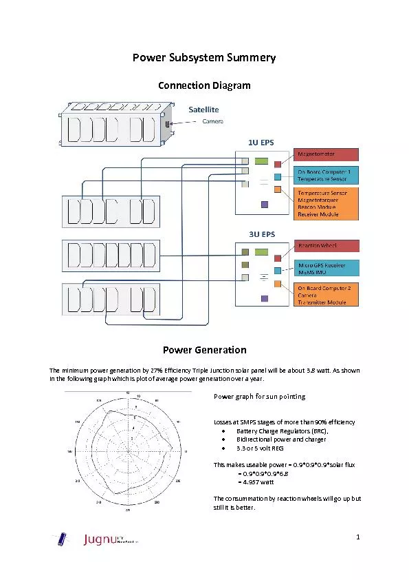
nnection Diagram
Power Generation
The minimum power generation by 27 Efficiency Triple Junction solar panel will be ab
out 38
watt As shown in the following
Download Presentation
"Power Subsystem Summery" is the property of its rightful owner. Permission is granted to download and print materials on this website for personal, non-commercial use only, provided you retain all copyright notices. By downloading content from our website, you accept the terms of this agreement.
Presentation Transcript
Transcript not available.