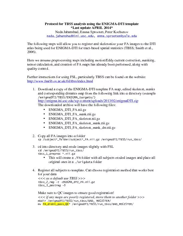
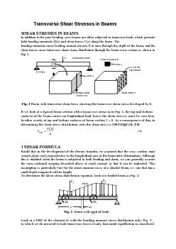
/
SES IN BEAMSIn addition to the pure bending case, beams are often subj SES IN BEAMSIn addition to the pure bending case, beams are often subj

SES IN BEAMSIn addition to the pure bending case, beams are often subj - PDF document

jane-oiler
jane-oiler . @jane-oiler
Follow
432 views
Uploaded On 2015-10-20

SES IN BEAMSIn addition to the pure bending case, beams are often subj - PPT Presentation

Resultant Shear ForceShear stress Transverse Force Crosssection aaArea A Area A aa 0 at thetop surface surfaces of the beam carries no longitudinal load hence the shear stresses must be zero he ID: 166962

Resultant Shear ForceShear stress Transverse

Share:

Link:

Embed:

Download Presentation from below link

Download Pdf The PPT/PDF document "SES IN BEAMSIn addition to the pure bend..." is the property of its rightful owner. Permission is granted to download and print the materials on this web site for personal, non-commercial use only, and to display it on your personal computer provided you do not modify the materials and that you retain all copyright notices contained in the materials. By downloading content from our website, you accept the terms of this agreement.


Presentation Transcript

SES IN BEAMSIn addition to the pure bending case, beams are often subjected to transverse loads which generate di bending moments cause bending normal stresses to arise through the depth of the beam, and the shear forces cause transverse shear-stress distribution through the beam cross section as shown in Resultant Shear ForceShear stress Transverse Force Cross-section a-aArea A Area A aa = 0 at thetop surface surfaces of the beam carries no longitudinal load, hence the shear stresses must be zero here. In other words, at top and bottom surfaces of beam section = 0. As a consequence of this, in determining the shear stress dist A Recall that in the development of the flexure formula, we assumed that the cross section must remain plane and perpendicular to the longitudinal axis of the beam after deformation. Although F1F2 M1 M2 in which we do not need to look transverse forces if only horizontal equilib dx M(x)M(x)+dM(x) dxdxM(x)+dM(x) dxdx N.A.Summing the forces horizontally on this infinitesimal element, the stresses due to the bending moments only form a couple, therefore the force resultant is equal to zero horizontally. Consider now a segment of this element a distance above the N.A. up to the top of the element. In order for it to be in equilibrium, a shear stress top dx M(x)M(x)+dM(x) dxdxM(x)+dM(x) dxdx N.A. y dy N.A. dx xy t(y) y dy topLet the width of the section at a distance from the be a function of and call it “)”. Applying the horizontal equilibrium equation, gives: ()()()toptopSubstituting for the magnitude of the stresses using ETB gives: ()() ()()toptopSimplifying and dividing by ) gives: () topBut since dx then, the Shear Stress Distribution is given by: ()() top where: the shear force carried by the section, found from the shear force diagram the second moment of area the sectional width at the distance from the ()() top is the top (or bottom) portion of the member’s cross-sectional area, defined from the section where ) is measured, and is the distance to the centroid of , measured from the Neutral Axis. ul b h NA y y’ A’ Centroidof A’ NA Paraboliccurve maxmax Shear Stress distribution The distribution of the shear stress throughout the cross section due to a shear force can be determined by computing the shear stress at an arbitrary height from the Neutral Axis. The second moment of entire area: 12 , applying the shear formula, Eq. (7.3), we have Š=׊×==22332246 12 421yhbhVbbhbyhVItVQ The result indicates that the shear stress distribution over the cross section is parabolic, as plotted in Fig. 7.5. The shear force intensity varies from zero at the top and bottom, From Eq. (7.5), the maximum shear stress that occurs at the Neutral Axis is A V.max51= This same value for can be obtained directly from the shear formula , by realizing that max occurs where is largest. By inspection, will be a maximum when the area above (or below) the neutral axis is considered, that is By comparison, ned from Eq. ( Lecture Notes of Mechanics of Solids, Chapter 7 In the previous chapters, we developed methods for determining the stress distribution in a member subjected to different types of load such as an axial force or a transverse shear force (Chapter 2), a torsional moment (Chapter 4), and a bending moment (Chapter 6). Most often, the cross section of a member is subjected to several of these loadings . As we shall see presently, we may combine the knowledge that we have acquired in the previous chapters. As long as the relationship between stress and the loads is linear and the geometry of the member would not undergo significant change when the loads are applied, the principle of superposition can be used as shown in Chapter 6. Here we are going to discuss the situation due to tensile force and transverse load , as shown in Table 7.1. Superposition of individual loads Bending normal Total normal stress TorsionalLoad(Torque BendingLoad(TransverseForce CombinedLoadsStressDistributionsStressesStresses Produced by Each Load Individually B x AD B N.A. A P PTABD N.A.x B AD F F avgTensile average normal stressavgTorsionalshear stressTransverse shear stress T B ADC CB AD M A,C A,C B ADC  B ADC Total shear stress at AxialLoad(Force y N.A. N.A. Lecture Notes of Mechanics of Solids, Chapter 7 Example 7.2: Two forces =15N are applied to the shaft with a radius of as shown. Determine the maximum normal and shear stresses developed in the shaft. PABD .x =100mm =50mm ABD .x F F =100mm yzy Step 0: Determine the geometrical properties of cross section: Area of cross section: Polar moment of inertia: Second moment of area: First moment of semicircle: Step 1: Move eccentric force to the center of the shaft This causes a uniform torsional moment (Torque) about axis by T=Pa=180000.05=900Nas shown. Centric force also will produce a varying bending moment ) along axis . Axial force leads to a constant average compressive normal stress at cross sections along the shaft. Step 2: Determine the maximum bending moment max and maximum shear force max B N.A. D P y Loading DiagramBending Moment Diagram Shear Force Diagram0.1 From the shear force and bending moment diagrams, one can identify that the shear force is uniform along the shaft with 18000N, and the maximum bending moment occurs at the section ABCD with a magnitude of max = Pb=180000.1=1800N. So the critical section is ABCD. Step 3: Apply the superposition for determining the maximum normal stress The maximum compressive stress occurs at point B, where both the maximum bending moment maxand axial force will form a highest combined compressive stress as MPa.. . . . I yM A Pmax298402869311 10 125 02 10 257 Step 4: Apply the superposition for determining the maximum shear stresses As shown in table 7.1, the maximum shear stress occurs at point C, where both the transverse shear force V=P and the torsional moment T=Pa give a highest combined shear stress as The max twist shear stress MPa . . J 71 10 251 (at outer surface) The max shear stress in bending () The total combined max shear stress: Lecture Notes of Mechanics of Solids, Chapter 7 In the previous chapters, we developed methods for determining the stress distribution in a member subjected to different types of load such as an axial force or a transverse shear force (Chapter 2), a torsional moment (Chapter 4), and a bending moment (Chapter 6). Most often, the cross section of a member is subjected to several of these loadings . As we shall see presently, we may combine the knowledge that we have acquired in the previous chapters. As long as the relationship between stress and the loads is linear and the geometry of the member would not undergo significant change when the loads are applied, the principle of superposition can be used as shown in Chapter 6. Here we are going to discuss the situation due to tensile force and transverse load , as shown in Table 7.1. Superposition of individual loads Bending normal Total normal stress TorsionalLoad(Torque BendingLoad(TransverseForce CombinedLoadsStressDistributionsStressesStresses Produced by Each Load Individually B x AD B N.A. A P PTABD N.A.x B AD F F avgTensile average normal stressavgTorsionalshear stressTransverse shear stress T B ADC CB AD M A,C A,C B ADC  B ADC Total shear stress at AxialLoad(Force y N.A. N.A. Lecture Notes of Mechanics of Solids, Chapter 7 In the previous chapters, we developed methods for determining the stress distribution in a member subjected to different types of load such as an axial force or a transverse shear force the cross section of a member is subjected to several of these loadings . As we shall see presently, we may combine the knowledge that we have acquired in the previous chapters. As long as the relationship between stress and the loads is linear and the geometry of the member would not undergo significant change when the loads are applied, the principle of superposition can be used as shown in Chapter 6. Here we are going to discuss the situation due to tensile force and transverse load , as shown in Table 7.1. Superposition of individual loads Bending normal Total normal stress TorsionalLoad(Torque BendingLoad(TransverseForce CombinedLoadsStressDistributionsStressesStresses Produced by Each Load Individually B x AD B N.A. A P PTABD N.A.x B AD F F avgTensile average normal stressavgTorsionalshear stressTransverse shear stress T B ADC CB AD M A,C A,C B ADC  B ADC Total shear stress at AxialLoad(Force y N.A. N.A. Lecture Notes of Mechanics of Solids, Chapter 7 In the previous chapters, we developed methods for determining the stress distribution in a the cross section of a member is subjected to several of these loadings . As we shall see presently, we may combine the knowledge that we have acquired in the previous chapters. As long as the relationship between stress and the loads is linear and the geometry of the member would not undergo significant change when the loads are applied, the principle of superposition can be used as shown in Chapter 6. Here we are going to discuss the situation due to tensile force and transverse load , as shown in Table 7.1. Superposition of individual loads Bending normal Total normal stress TorsionalLoad(Torque BendingLoad(TransverseForce CombinedLoadsStressDistributionsStressesStresses Produced by Each Load Individually B x AD B N.A. A P PTABD N.A.x B AD F F avgTensile average normal stressavgTorsionalshear stressTransverse shear stress T B ADC CB AD M A,C A,C B ADC  B ADC Total shear stress at AxialLoad(Force y N.A. N.A. Lecture Notes of Mechanics of Solids, Chapter 7 In the previous chapters, we developed methods for determining the stress distribution in a the cross section of a member is subjected to several of these loadings . As we shall see presently, we may combine the knowledge that we have acquired in the previous chapters. As long as the relationship between stress and the loads is linear and the geometry of the member would not undergo significant change when the loads are applied, the principle of superposition can be used as shown in Chapter 6. Here we are going to discuss the situation due to tensile force and transverse load , as shown in Table 7.1. Superposition of individual loads Bending normal Total normal stress TorsionalLoad(Torque BendingLoad(TransverseForce CombinedLoadsStressDistributionsStressesStresses Produced by Each Load Individually B x AD B N.A. A P PTABD N.A.x B AD F F avgTensile average normal stressavgTorsionalshear stressTransverse shear stress T B ADC CB AD M A,C A,C B ADC  B ADC Total shear stress at AxialLoad(Force y N.A. N.A. Lecture Notes of Mechanics of Solids, Chapter 7 In the previous chapters, we developed methods for determining the stress distribution in a the cross section of a member is subjected to several of these loadings . As we shall see presently, we may combine the knowledge that we have acquired in the previous chapters. As long as the relationship between stress and the loads is linear and the geometry of the member would not undergo significant change when the loads are applied, the principle of superposition can be used as shown in Chapter 6. Here we are going to discuss the situation due to tensile force and transverse load , as shown in Table 7.1. Superposition of individual loads Bending normal Total normal stress TorsionalLoad(Torque BendingLoad(TransverseForce CombinedLoadsStressDistributionsStressesStresses Produced by Each Load Individually B x AD B N.A. A P PTABD N.A.x B AD F F avgTensile average normal stressavgTorsionalshear stressTransverse shear stress T B ADC CB AD M A,C A,C B ADC  B ADC Total shear stress at AxialLoad(Force y N.A. N.A. Lecture Notes of Mechanics of Solids, Chapter 7 In the previous chapters, we developed methods for determining the stress distribution in a the cross section of a member is subjected to several of these loadings . As we shall see presently, we may combine the knowledge that we have acquired in the previous chapters. As long as the relationship between stress and the loads is linear and the geometry of the member would not undergo significant change when the loads are applied, the principle of superposition can be used as shown in Chapter 6. Here we are going to discuss the situation due to tensile force and transverse load , as shown in Table 7.1. Superposition of individual loads Bending normal Total normal stress TorsionalLoad(Torque BendingLoad(TransverseForce CombinedLoadsStressDistributionsStressesStresses Produced by Each Load Individually B x AD B N.A. A P PTABD N.A.x B AD F F avgTensile average normal stressavgTorsionalshear stressTransverse shear stress T B ADC CB AD M A,C A,C B ADC  B ADC Total shear stress at AxialLoad(Force y N.A. N.A. Lecture Notes of Mechanics of Solids, Chapter 7 In the previous chapters, we developed methods for determining the stress distribution in a the cross section of a member is subjected to several of these loadings . As we shall see presently, we may combine the knowledge that we have acquired in the previous chapters. As long as the relationship between stress and the loads is linear and the geometry of the member would not undergo significant change when the loads are applied, the principle of superposition can be used as shown in Chapter 6. Here we are going to discuss the situation due to tensile force and transverse load , as shown in Table 7.1. Superposition of individual loads Bending normal Total normal stress TorsionalLoad(Torque BendingLoad(TransverseForce CombinedLoadsStressDistributionsStressesStresses Produced by Each Load Individually B x AD B N.A. A P PTABD N.A.x B AD F F avgTensile average normal stressavgTorsionalshear stressTransverse shear stress T B ADC CB AD M A,C A,C B ADC  B ADC Total shear stress at AxialLoad(Force y N.A. N.A. Lecture Notes of Mechanics of Solids, Chapter 7 In the previous chapters, we developed methods for determining the stress distribution in a the cross section of a member is subjected to several of these loadings . As we shall see presently, we may combine the knowledge that we have acquired in the previous chapters. As long as the relationship between stress and the loads is linear and the geometry of the member would not undergo significant change when the loads are applied, the principle of superposition can be used as shown in Chapter 6. Here we are going to discuss the situation due to tensile force and transverse load , as shown in Table 7.1. Superposition of individual loads Bending normal Total normal stress TorsionalLoad(Torque BendingLoad(TransverseForce CombinedLoadsStressDistributionsStressesStresses Produced by Each Load Individually B x AD B N.A. A P PTABD N.A.x B AD F F avgTensile average normal stressavgTorsionalshear stressTransverse shear stress T B ADC CB AD M A,C A,C B ADC  B ADC Total shear stress at AxialLoad(Force y N.A. N.A. Lecture Notes of Mechanics of Solids, Chapter 7 In the previous chapters, we developed methods for determining the stress distribution in a the cross section of a member is subjected to several of these loadings . As we shall see presently, we may combine the knowledge that we have acquired in the previous chapters. As long as the relationship between stress and the loads is linear and the geometry of the member would not undergo significant change when the loads are applied, the principle of superposition can be used as shown in Chapter 6. Here we are going to discuss the situation due to tensile force and transverse load , as shown in Table 7.1. Superposition of individual loads Bending normal Total normal stress TorsionalLoad(Torque BendingLoad(TransverseForce CombinedLoadsStressDistributionsStressesStresses Produced by Each Load Individually B x AD B N.A. A P PTABD N.A.x B AD F F avgTensile average normal stressavgTorsionalshear stressTransverse shear stress T B ADC CB AD M A,C A,C B ADC  B ADC Total shear stress at AxialLoad(Force y N.A. N.A. Lecture Notes of Mechanics of Solids, Chapter 7 In the previous chapters, we developed methods for determining the stress distribution in a the cross section of a member is subjected to several of these loadings . As we shall see presently, we may combine the knowledge that we have acquired in the previous chapters. As long as the relationship between stress and the loads is linear and the geometry of the member would not undergo significant change when the loads are applied, the principle of superposition can be used as shown in Chapter 6. Here we are going to discuss the situation due to tensile force and transverse load , as shown in Table 7.1. Superposition of individual loads Bending normal Total normal stress TorsionalLoad(Torque BendingLoad(TransverseForce CombinedLoadsStressDistributionsStressesStresses Produced by Each Load Individually B x AD B N.A. A P PTABD N.A.x B AD F F avgTensile average normal stressavgTorsionalshear stressTransverse shear stress T B ADC CB AD M A,C A,C B ADC  B ADC Total shear stress at AxialLoad(Force y N.A. N.A. Lecture Notes of Mechanics of Solids, Chapter 7 In the previous chapters, we developed methods for determining the stress distribution in a the cross section of a member is subjected to several of these loadings . As we shall see presently, we may combine the knowledge that we have acquired in the previous chapters. As long as the relationship between stress and the loads is linear and the geometry of the member would not undergo significant change when the loads are applied, the principle of superposition can be used as shown in Chapter 6. Here we are going to discuss the situation due to tensile force and transverse load , as shown in Table 7.1. Superposition of individual loads Bending normal Total normal stress TorsionalLoad(Torque BendingLoad(TransverseForce CombinedLoadsStressDistributionsStressesStresses Produced by Each Load Individually B x AD B N.A. A P PTABD N.A.x B AD F F avgTensile average normal stressavgTorsionalshear stressTransverse shear stress T B ADC CB AD M A,C A,C B ADC  B ADC Total shear stress at AxialLoad(Force y N.A. N.A. Lecture Notes of Mechanics of Solids, Chapter 7 In the previous chapters, we developed methods for determining the stress distribution in a the cross section of a member is subjected to several of these loadings . As we shall see presently, we may combine the knowledge that we have acquired in the previous chapters. As long as the relationship between stress and the loads is linear and the geometry of the member would not undergo significant change when the loads are applied, the principle of superposition can be used as shown in Chapter 6. Here we are going to discuss the situation due to tensile force and transverse load , as shown in Table 7.1. Superposition of individual loads Bending normal Total normal stress TorsionalLoad(Torque BendingLoad(TransverseForce CombinedLoadsStressDistributionsStressesStresses Produced by Each Load Individually B x AD B N.A. A P PTABD N.A.x B AD F F avgTensile average normal stressavgTorsionalshear stressTransverse shear stress T B ADC CB AD M A,C A,C B ADC  B ADC Total shear stress at AxialLoad(Force y N.A. N.A. Lecture Notes of Mechanics of Solids, Chapter 7 In the previous chapters, we developed methods for determining the stress distribution in a the cross section of a member is subjected to several of these loadings . As we shall see presently, we may combine the knowledge that we have acquired in the previous chapters. As long as the relationship between stress and the loads is linear and the geometry of the member would not undergo significant change when the loads are applied, the principle of superposition can be used as shown in Chapter 6. Here we are going to discuss the situation due to tensile force and transverse load , as shown in Table 7.1. Superposition of individual loads Bending normal Total normal stress TorsionalLoad(Torque BendingLoad(TransverseForce CombinedLoadsStressDistributionsStressesStresses Produced by Each Load Individually B x AD B N.A. A P PTABD N.A.x B AD F F avgTensile average normal stressavgTorsionalshear stressTransverse shear stress T B ADC CB AD M A,C A,C B ADC  B ADC Total shear stress at AxialLoad(Force y N.A. N.A. Lecture Notes of Mechanics of Solids, Chapter 7 In the previous chapters, we developed methods for determining the stress distribution in a the cross section of a member is subjected to several of these loadings . As we shall see presently, we may combine the knowledge that we have acquired in the previous chapters. As long as the relationship between stress and the loads is linear and the geometry of the member would not undergo significant change when the loads are applied, the principle of superposition can be used as shown in Chapter 6. Here we are going to discuss the situation due to tensile force and transverse load , as shown in Table 7.1. Superposition of individual loads Bending normal Total normal stress TorsionalLoad(Torque BendingLoad(TransverseForce CombinedLoadsStressDistributionsStressesStresses Produced by Each Load Individually B x AD B N.A. A P PTABD N.A.x B AD F F avgTensile average normal stressavgTorsionalshear stressTransverse shear stress T B ADC CB AD M A,C A,C B ADC  B ADC Total shear stress at AxialLoad(Force y N.A. N.A. Lecture Notes of Mechanics of Solids, Chapter 7 In the previous chapters, we developed methods for determining the stress distribution in a the cross section of a member is subjected to several of these loadings . As we shall see presently, we may combine the knowledge that we have acquired in the previous chapters. As long as the relationship between stress and the loads is linear and the geometry of the member would not undergo significant change when the loads are applied, the principle of superposition can be used as shown in Chapter 6. Here we are going to discuss the situation due to tensile force and transverse load , as shown in Table 7.1. Superposition of individual loads Bending normal Total normal stress TorsionalLoad(Torque BendingLoad(TransverseForce CombinedLoadsStressDistributionsStressesStresses Produced by Each Load Individually B x AD B N.A. A P PTABD N.A.x B AD F F avgTensile average normal stressavgTorsionalshear stressTransverse shear stress T B ADC CB AD M A,C A,C B ADC  B ADC Total shear stress at AxialLoad(Force y N.A. N.A. Lecture Notes of Mechanics of Solids, Chapter 7 In the previous chapters, we developed methods for determining the stress distribution in a the cross section of a member is subjected to several of these loadings . As we shall see presently, we may combine the knowledge that we have acquired in the previous chapters. As long as the relationship between stress and the loads is linear and the geometry of the member would not undergo significant change when the loads are applied, the principle of superposition can be used as shown in Chapter 6. Here we are going to discuss the situation due to tensile force and transverse load , as shown in Table 7.1. Superposition of individual loads Bending normal Total normal stress TorsionalLoad(Torque BendingLoad(TransverseForce CombinedLoadsStressDistributionsStressesStresses Produced by Each Load Individually B x AD B N.A. A P PTABD N.A.x B AD F F avgTensile average normal stressavgTorsionalshear stressTransverse shear stress T B ADC CB AD M A,C A,C B ADC  B ADC Total shear stress at AxialLoad(Force y N.A. N.A. Lecture Notes of Mechanics of Solids, Chapter 7 In the previous chapters, we developed methods for determining the stress distribution in a the cross section of a member is subjected to several of these loadings . As we shall see presently, we may combine the knowledge that we have acquired in the previous chapters. As long as the relationship between stress and the loads is linear and the geometry of the member would not undergo significant change when the loads are applied, the principle of superposition can be used as shown in Chapter 6. Here we are going to discuss the situation due to tensile force and transverse load , as shown in Table 7.1. Superposition of individual loads Bending normal Total normal stress TorsionalLoad(Torque BendingLoad(TransverseForce CombinedLoadsStressDistributionsStressesStresses Produced by Each Load Individually B x AD B N.A. A P PTABD N.A.x B AD F F avgTensile average normal stressavgTorsionalshear stressTransverse shear stress T B ADC CB AD M A,C A,C B ADC  B ADC Total shear stress at AxialLoad(Force y N.A. N.A. Lecture Notes of Mechanics of Solids, Chapter 7 In the previous chapters, we developed methods for determining the stress distribution in a the cross section of a member is subjected to several of these loadings . As we shall see presently, we may combine the knowledge that we have acquired in the previous chapters. As long as the relationship between stress and the loads is linear and the geometry of the member would not undergo significant change when the loads are applied, the n bed . Hoithe situation due to tensile force and transverse load , as shown in Table 7.1. Superposition of individual loads Bending normal Total normal stress TorsionalLoad(Torque BendingLoad(TransverseForce CombinedLoadsStressDistributionsStressesStresses Produced by Each Load Individually B x AD B N.A. A P PTABD N.A.x B AD F F avgTensile average normal stressavgTorsionalshear stressTransverse shear stress T B ADC CB AD M A,C A,C B ADC  B ADC Total shear stress at AxialLoad(Force y N.A. N.A. Lecture Notes of Mechanics of Solids, Chapter 7 In the previous chapters, we developed methods for determining the stress distribution in a the cross section of a member is subjected to several of these loadings . As we shall see presently, we may combine the knowledge that we have acquired in the previous chapters. As long as the relationship between stress and the loads is linear and the geometry of the member would not undergo significant change when the loads are applied, the n bed. Hoithe situation due to tensile force and transverse load , as shown in Table 7.1. Superposition of individual loads Bending normal Total normal stress TorsionalLoad(Torque BendingLoad(TransverseForce CombinedLoadsStressDistributionsStressesStresses Produced by Each Load Individually B x AD B N.A. A P PTABD N.A.x B AD F F avgTensile average normal stressavgTorsionalshear stressTransverse shear stress T B ADC CB AD M A,C A,C B ADC  B ADC Total shear stress at AxialLoad(Force y N.A. N.A. Lecture Notes of Mechanics of Solids, Chapter 7 In the previous chapters, we developed methods for determining the stress distribution in a the cross section of a member is subjected to several of these loadings . As we shall see presently, we may combine the knowledge that we have acquired in the previous chapters. As long as the relationship between stress and the loads is linear and the geometry of the member would not undergo significant change when the loads are applied, the n bed. Hoi oad Superposition of individual loads Bending normal Total normal stress TorsionalLoad(Torque BendingLoad(TransverseForce CombinedLoadsStressDistributionsStressesStresses Produced by Each Load Individually B x AD B N.A. A P PTABD N.A.x B AD F F avgTensile average normal stressavgTorsionalshear stressTransverse shear stress T B ADC CB AD M A,C A,C B ADC  B ADC Total shear stress at AxialLoad(Force y N.A. N.A. Lecture Notes of Mechanics of Solids, Chapter 7 In the previous chapters, we developed methods for determining the stress distribution in a the cross section of a member is subjected to several of these loadings . As we shall see presently, we may combine the knowledge that we have acquired in the previous chapters. As long as the relationship between stress and the loads is linear and the geometry of the member would not undergo significant change when the loads are applied, the n bed. Hoi oadds Bending normal Total normal stress TorsionalLoad(Torque BendingLoad(TransverseForce CombinedLoadsStressDistributionsStressesStresses Produced by Each Load Individually B x AD B N.A. A P PTABD N.A.x B AD F F avgTensile average normal stressavgTorsionalshear stressTransverse shear stress T B ADC CB AD M A,C A,C B ADC  B ADC Total shear stress at AxialLoad(Force y N.A. N.A. In the previous chapters, we developed methods for determining the stress distribution in a the cross section of a member is subjected to several of these loadings . As we shall see presently, we may combine the knowledge that we have acquired in the previous chapters. As long as the relationship between stress and the loads is linear and the geometry of the member would not undergo significant change when the loads are applied, the n bed. Hoi oadds Bending normal Total normal stress TorsionalLoad(Torque BendingLoad(TransverseForce CombinedLoadsStressDistributionsStressesStresses Produced by Each Load Individually B x AD B N.A. A P PTABD N.A.x B AD F F avgTensile average normal stressavgTorsionalshear stressTransverse shear stress T B ADC CB AD M A,C A,C B ADC  B ADC Total shear stress at AxialLoad(Force y N.A. N.A. Example 7.2: Two forces =15N are applied to the shaft with a radius of as shown. Determine the maximum normal and shear stresses developed in the shaft. PABD N.A.x C b=100mm a=50mm PABD N.A.x C F FT=Pa b=100mm zyzy Step 0: Determine the geometrical properties of cross section: Area of cross section: Polar moment of inertia: Second moment of area: First moment of semicircle: Step 1: Move eccentric force to the center of the shaft This causes a uniform torsional moment (Torque) about axis by T=Pa=180000.05=900Nas shown. Centric force also will produce a varying bending moment ) along axis . Axial force leads to a constant average compressive normal stress at cross sections along the shaft. Step 2: Determine the maximum bending moment max and maximum shear force max B N.A. AD P y Loading DiagramBending Moment Diagram Shear Force Diagram0.1 From the shear force and bending moment diagrams, one can identify that the shear force is uniform along the shaft with 18000N, and the maximum bending moment occurs at the section ABCD with a magnitude of max = Pb=180000.1=1800N. So the critical section is ABCD. Step 3: Apply the superposition for determining the maximum normal stress The maximum compressive stress occurs at point B, where both the maximum bending moment maxand axial force will form a highest combined compressive stress as MPa... . . . I yM A PmaxmaxBmax33298402869311 10 7 125 0201800 10 257 1 Step 4: Apply the superposition for determining the maximum shear stresses As shown in table 7.1, the maximum shear stress occurs at point C, where both the transverse shear force V=P and the torsional moment T=Pa give a highest combined shear stress as The max twist shear stress MPa. . . J TRTmax6371 10 3 251 (at outer surface) The max shear stress in bending ()()()() The total combined max shear stress: Example 7.2: Two forces =15N are applied to the shaft with a radius of as shown. Determine the maximum normal and shear stresses developed in the shaft. PABD N.A.x C b=100mm a=50mm PABD N.A.x C F FT=Pa b=100mm zyzy Step 0: Determine the geometrical properties of cross section: Area of cross section: Polar moment of inertia: Second moment of area: First moment of semicircle: Step 1: Move eccentric force to the center of the shaft This causes a uniform torsional moment (Torque) about axis by T=Pa=180000.05=900Nas shown. Centric force also will produce a varying bending moment ) along axis . Axial force leads to a constant average compressive normal stress at cross sections along the shaft. Step 2: Determine the maximum bending moment max and maximum shear force max B N.A. AD P y Loading DiagramBending Moment Diagram Shear Force Diagram0.1 From the shear force and bending moment diagrams, one can identify that the shear force is uniform along the shaft with 18000N, and the maximum bending moment occurs at the section ABCD with a magnitude of max = Pb=180000.1=1800N. So the critical section is ABCD. Step 3: Apply the superposition for determining the maximum normal stress The maximum compressive stress occurs at point B, where both the maximum bending moment maxand axial force will form a highest combined compressive stress as MPa... . . . I yM A PmaxmaxBmax33298402869311 10 7 125 0201800 10 257 1 Step 4: Apply the superposition for determining the maximum shear stresses As shown in table 7.1, the maximum shear stress occurs at point C, where both the transverse shear force V=P and the torsional moment T=Pa give a highest combined shear stress as The max twist shear stress MPa. . . J TRTmax6371 10 3 251 (at outer surface) The max shear stress in bending ()()()() The total combined max shear stress: Example 7.2: Two forces =15N are applied to the shaft with a radius of as shown. Determine the maximum normal and shear stresses developed in the shaft. PABD N.A.x C b=100mm a=50mm PABD N.A.x C F FT=Pa b=100mm zyzy Step 0: Determine the geometrical properties of cross section: Area of cross section: Polar moment of inertia: Second moment of area: First moment of semicircle: Step 1: Move eccentric force to the center of the shaft This causes a uniform torsional moment (Torque) about axis by T=Pa=180000.05=900Nas shown. Centric force also will produce a varying bending moment ) along axis . Axial force leads to a constant average compressive normal stress at cross sections along the shaft. Step 2: Determine the maximum bending moment max and maximum shear force max B N.A. AD P y Loading DiagramBending Moment Diagram Shear Force Diagram0.1 From the shear force and bending moment diagrams, one can identify that the shear force is uniform along the shaft with 18000N, and the maximum bending moment occurs at the section ABCD with a magnitude of max = Pb=180000.1=1800N. So the critical section is ABCD. Step 3: Apply the superposition for determining the maximum normal stress The maximum compressive stress occurs at point B, where both the maximum bending moment maxand axial force will form a highest combined compressive stress as MPa... . . . I yM A PmaxmaxBmax33298402869311 10 7 125 0201800 10 257 1 Step 4: Apply the superposition for determining the maximum shear stresses As shown in table 7.1, the maximum shear stress occurs at point C, where both the transverse shear force V=P and the torsional moment T=Pa give a highest combined shear stress as The max twist shear stress MPa. . . J TRTmax6371 10 3 251 (at outer surface) The max shear stress in bending ()()()() The total combined max shear stress: ul b h NA y y’ A’ Centroidof A’ NA Paraboliccurve maxmax Shear Stress distribution The distribution of the shear stress throughout the cross section due to a shear force can be determined by computing the shear stress at an arbitrary height from the Neutral Axis. The second moment of entire area: 12 , applying the shear formula, Eq. (7.3), we have Š=׊×==22332246 12 421yhbhVbbhbyhVItVQ The result indicates that the shear stress distribution over the cross section is parabolic, as . 5. The hear fs from From Eq. (7.5), the maximum shear stress that occurs at the Neutral Axis is A V.max51= This same value for can be obtained directly from the shear formula , by realizing that max occurs where is largest. By inspection, will be a maximum when the area above (or below) the neutral axis is considered, that is By comparison, ned from Eq. ( ul b h NA y y’ A’ Centroidof A’ NA Paraboliccurve maxmax Shear Stress distribution The distribution of the shear stress throughout the cross section due to a shear force can be determined by computing the shear stress at an arbitrary height from the Neutral Axis. The second moment of entire area: 12 , applying the shear formula, Eq. (7.3), we have Š=׊×==22332246 12 421yhbhVbbhbyhVItVQ The result indicates that the shear stress distribution over the cross section is parabolic, as . 5. The hear fs from umhathe A V.max51= This same value for can be obtained directly from the shear formula , by realizing that max occurs where is largest. By inspection, will be a maximum when the area above (or below) the neutral axis is considered, that is By comparison, ned from Eq. (