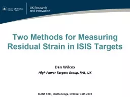
Targets Dan Wilcox High Power Targets Group RAL UK ICANS XXIII Chattanooga October 16th 2019 Outline Background Asymmetricclad strip method Neutron diffraction method Results and analysis ID: 801403
Download The PPT/PDF document "Two Methods for Measuring Residual Strai..." is the property of its rightful owner. Permission is granted to download and print the materials on this web site for personal, non-commercial use only, and to display it on your personal computer provided you do not modify the materials and that you retain all copyright notices contained in the materials. By downloading content from our website, you accept the terms of this agreement.
Slide1
Two Methods for Measuring Residual Strain in ISIS Targets
Dan Wilcox
High Power Targets Group, RAL, UK
ICANS XXIII, Chattanooga, October 16th 2019
Slide2Outline
Background
Asymmetric-clad strip method
Neutron diffraction method
Results and analysis
Implications for target design
Slide3Acknowledgements
Sample
manufacture –
Leslie Jones, Jeremy
Moor, Max Rowland, Peter
Webb
Asymmetric-clad
concept
– Peter
Loveridge
Instrument
scientists – Saurabh Kabra, Tung Lik Lee
ISIS management
– Ste Gallimore, David Jenkins
Slide4Background
ISIS operates two spallation targets; TS1 and TS2
Both have tungsten cores clad in tantalum for corrosion resistance
Any significant cladding breach means we have to replace the target
Causes activation of the cooling plant, which needs hands-on maintenance
Cladding is attached by Hot Isostatic Press (HIP)
Produces a strong bond with good thermal contact
High residual stress predicted from HIP – maybe more than beam heating
Exact amount of residual stress is a major unknown in current simulations*
*D. Wilcox, P. Loveridge, T. Davenne, L. Jones and D. Jenkins, "Stress levels and failure modes of tantalum-clad tungsten targets at ISIS," Journal of Nuclear Materials, vol. 506, pp. 76-82, 2018.
TS1
TS2
Slide5ISIS Target Manufacture
Tantalum can welded shut with tungsten core inside
Hot
Isostatic Press (HIP) process applies high temperature and pressure,
bonding
cladding
and core
Final machining to achieve dimensional
accuracy
Components of TS2 target HIP assembly
Slide6ISIS Target Manufacture
HIP cycle in detail:
Cladding deforms plastically under high pressure (140MPa)
Peak temperature is 1200°C, held for 2 hours; this relieves stress, but does not cause grain growth
Tantalum and tungsten are bonded
together
As the clad target cools below the annealing temperature, residual stress builds up due to different coefficients of thermal expansion:
Tungsten 4.5E-06/K
Tantalum 6.3E-06/K
A typical ISIS HIP cycle
Slide7Simplifying Assumptions
Simplifying assumptions for simulating residual stress:
All stress from welding and HIP pressure is relieved during HIPing
Stress due to final machining and plate welding is small compared to stress from HIPing, and can be ignored
Stress from HIP cooldown is relieved at first, but below a certain ‘lock-in’ temperature stress starts to builds up
Industry uses a stress relieving temperature of around 850°C
Lock-in
temperature estimated to be 500°C, but this needs validation
Slide8Asymmetric-Clad Strip Method
Provides a
simple, mechanical
method of measuring residual stress after HIPing
HIP a long strip
of
tungsten with asymmetric
tantalum
claddingThe strip should deflect in proportion to the residual stressCalculations predict a spherical surface, concave on the thick tantalum sideDimensions optimised to produce a measurable deflection without breaking the sample
Nominal dimensions of asymmetric-clad strip
Slide9Photos: Jeremy Moor
Manufacture
Manufactured
by Jeremy Moor and his team using the same materials and methods as ISIS
targets
Slide10Measurement
Sample was measured before and after HIP using a Faro Edge arm (laser scanner coordinate measuring machine)
Concave on thick tantalum side and almost spherical, as expected
Spherical surfaces fit the upper and lower faces with r
2
= 0.990
Cloud of points from Faro arm (above) and spherical fits to upper and lower surfaces (right)
Upper surface
Lower surface
Slide11Comparison with Theory
Compare fit and simulated radii of curvature
Estimates lock-in temperature at 385-450°C
To produce the measured deflection the tantalum must have yielded
Slide12Neutron Diffraction Method
ENGIN-X is an instrument on ISIS TS1 which uses neutron diffraction to make non-destructive strain measurements
“
The beamline is optimized for the measurement of strain, and thus stress, deep within a crystalline material, using the atomic lattice planes as an atomic 'strain gauge
'.”
https://www.isis.stfc.ac.uk/Pages/Engin-X.aspx
Good penetration depth even in Ta/W
1x1x18mm measurement volume
Cannot measure plastic strainStrains are calculated relative to an unstressed ‘d0’ measurement
The ENGIN-X instrument: measuring residual stress within friction stir welds on an Airbus prototype wing rib
Slide13Neutron diffraction experiment on ENGIN-X by Yanling Ma et al. on a TS1 plate*
Demonstrated that ENGIN-X can measure depths of up to 13mm in tantalum/tungsten in a reasonable length of time
*
Yanling
Ma et al., “An Experiment Using Neutron Diffraction to Investigate Residual Strain Distribution in a Hot Isostatic Pressed (HIPPED) Target Plate,” in Joint 3rd UK-China Steel Research Forum & 15th CMA-UK Conference on Materials Science and Engineering, 2014.
Prior Experiment by
Yanling
Ma et al.
Slide14Measured elastic strains are broadly consistent with the cladding being at the yield stress as predicted – however the sample was too thick to measure all three directions so this could not be confirmed
Engin
-X Strain Result (Y direction)
ANSYS Simulation of
Engin
-X Sample
≈ 600
Microstrain
662
Microstrain
-749
Microstrain
≈ -300
Microstrain
Prior Experiment by
Yanling
Ma et al.
Slide15ENGIN-X Measurements
Two experiments: October 2018 (3 days) and March 2019 (2 days)
Aims – measure a detailed through-thickness strain profile
–
check uniformity of strain profile with position
– measure all 3 strain components at every point
Clamp
this end
50mm
50mm
20mm
Z
X
Y
10mm
10mm
9 Points
3, 9, 3
Points
3
Points
Slide16ENGIN-X Measurements
Sample rotated part way through to measure all 3 strain components
Normal direction measured twice
Photos courtesy of Tung Lik Lee
Slide17ENGIN-X Results – Part 1
Similar profiles in x and y, as expected
Good repeatability between repeat measurements
Quite good agreement with simulation apart from through-thickness (z) strain in tantalum
Slide18Changes for Second ENGIN-X Run
Previous ‘d0’ samples may not have been truly unstressed
Tantalum d0 sample was rolled and annealed
Tungsten d0 sample was forged, but probably not annealed
Repeated measurement with new d0 samples
Tungsten
sample
cut into combs to relieve stress from forging
Previous W sample had higher normal strain – possibly due to forgingPrevious Ta sample the same to within the ≈100 microstrain uncertainty
Also re-measured old locations and added more measurement points
Strain in
previous
d0 samples
In Plane
Normal
Tungsten
91
-221
Tantalum
-70
20
All values in
microstrain
Slide19HIP Effects on Nominally Unstressed Samples
Second run also looked at the stress change after
HIPing
in pure tantalum and pure
tungsten
HIP may change the atomic spacing and therefore d0 measurement
An
exact copy of each d0 sample was put through a standard ISIS HIP cycle
HIPing induces a strain which is compressive in W, tensile in
TaChanges are anisotropic, which was unexpected and makes it difficult to apply d0 corrections to other geometry e.g. the strip
Strain change due to
HIPing
In Plane
Normal
Tungsten
-294
-58
Tantalum
309
83
All values in
microstrain
Slide20ENGIN-X Results – Part 2
Good
repeatability between different locations and
times
No choice of d0 measurement improves the fit for all materials and directions
Slide21Conclusions from Experiments
Presence of large tensile residual stress in cladding confirmed by physical test and neutron measurement
Simulations with lock-in temperature ≈ 400°C predict the shape of the deformed strip, but do not explain all the details seen by ENGIN-X
HIPing
produces unexpected changes in neutron diffraction strain measurements of pure
tantalum
and
tungsten
samplesDifferences in ENGIN-X data vs simulation may be due to:Large uncertainties relative to measurement (high Young’s mod of Ta/W)
Creep of tantalum during cooldown after HIPingDeformed grains or other microstructural effects => anisotropic propertiesNo stress relieving was observed over time. Residual stress may relieve in-beam, but this would be difficult to measure.
Slide22Implications for Target Design
Large residual stress confirmed, so this should be taken into account in future target analysis work
High tensile stress will reduce fatigue life of the cladding, although current ISIS targets have a large safety factor even with this included
Limited data on combined radiation damage and fatigue effects
If tantalum ductility is lost this may present a problem
Not currently an issue, but could be for potential ISIS-2 targets
Continuing to develop our understanding of failure modes will enable more optimised targets and higher beam powers in future