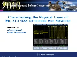
Networks Presented by Johnnie Hancock Agilent Technologies 2 Objectives Learn how to quickly verify the electricalphysical layer input and output characteristics of MILSTD 1553 differential serial buses using a Digital Storage Oscilloscope DSO with MILSTD 1553 bus decoding and triggerin ID: 496577
Download Presentation The PPT/PDF document "Characterizing the Physical Layer of MIL..." is the property of its rightful owner. Permission is granted to download and print the materials on this web site for personal, non-commercial use only, and to display it on your personal computer provided you do not modify the materials and that you retain all copyright notices contained in the materials. By downloading content from our website, you accept the terms of this agreement.
Slide1
Characterizing the Physical Layer of MIL-STD 1553 Differential Bus Networks
Presented by:Johnnie HancockAgilent TechnologiesSlide2
2
ObjectivesLearn how to quickly verify the electrical/physical layer input and output characteristics of MIL-STD 1553 differential serial buses using a Digital Storage Oscilloscope (DSO) with MIL-STD 1553 bus decoding and triggering capability.
Learn how eye-diagram mask testing can provide a composite measure of the signal integrity of your MIL-STD 1553 differential bus. Slide3
3
Agenda
MIL-STD 1553 Protocol & Timing Overview
MIL-STD 1553 Electrical/Physical Layer Requirements
Triggering and Decoding MIL-STD 1553 Serial Buses
Isolating Physical Layer Measurements on Remote Terminal (RT) and Bus Controller (BC) generated Signals
MIL-STD 1553 Eye-diagram Mask Testing
Clock Recovery TechniqueSlide4
4
MIL-STD 1553 Protocol & Timing Overview
Word Length = 20 bits (3-bit Sync field, 16-bit content field, 1-bit parity field)
Word Types:
Command (Packets transmitted by BCs)
Status (Packets transmitted by RTs)
Data (Packets transmitted by BCs and RTs)
Baud Rate = 1 Mb/s
Encoding = Manchester II Bi-phase (except 3-bit Sync field) Slide5
5
Manchester II Bi-phase Encoding
NRZ Encoding
High during middle of bit time = 1
Low during middle of bit time = 0
Manchester II Bi-phase Encoding
High to low transition in middle of bit time = 1
Low to high transition in middle of bit time = 0Slide6
6
Message Formats
(Master/Slave Relationship)
Example #1: BC to RT Transfers (BC sends data to RT)
Note: Signals probed at BC input/output test plane
A Packet - Command Word from BC to RTA = 0F w/ receive bit set: “Get ready accept data.”
A
A
B Packets - 5 Data Words transmitted from BC to RT
B
B
B
B
B
B
B
B
C Packet - Status Word from RTA = 0F: “Got it!”
C
CSlide7
7
Message Formats
(Master/Slave Relationship)
Example #2: RT to BC Transfers (BC requests data from RT)
Note: Signals probed at RT input/output test plane
A Packet - Command Word from BC to RTA = 02 w/ transmit bit set: “Send me data.”
A
A
B Packet - Status Word from RTA = 02: “Here it comes!”
B
B
C Packets - 4 Data Words transmitted from RT to BC
C
C
C
C
C
C
CSlide8
8
Message Formats
(Master/Slave Relationship)
Example #3: RT to RT Transfers (BC requests RT “2” to send data to RT “1”)
Scope waveforms not available
A Packet - Command Word from BC to RTA “1” w/ receive bit set: “Get ready accept data.”
A
A
B Packet – Command Word from BC to RTA “2” w/ transmit bit set: “Send data to RT “2”.”
B
B
C Packet – Status Word from RTA “2”: “Here it comes!”
C
C
E
E Packet – Status Word from RTA “1”: “Got it!”
E
D
D
D
D Packets - N Data Words transmitted from RT “2” to RT “1”
D
D
D
D
Note: Signals probed at RT2 input/output test planeSlide9
9
Primary Electrical/Physical Layer Specifications
Transformer Coupled
Direct Coupled
Terminal Output Specs
Voltage Swing
18 to 27 V p-p
6 to 9 V p-p
Overshoot
≤ 900 mV
≤ 300 mV
Noise
≤ 14 mV RMS
≤ 5 mV RMS
Transition Time
100 to 300 ns (10/90)
Zero Crossing Distortion
≤ 25 ns
≤ 25 ns
Output Symmetry
< 250 mV
< 90 mV
Terminal Input Specs
Voltage Swing
0.86 to 14 V p-p
1.2 to 20 V p-p
Input Rejection V
≤ 0.2 V
≤ 0.28 V
Zero Crossing Distortion
≤ 150 ns
≤ 150 ns
Other Important Timing Parameters
Intermessage Gap: ≥ 4 µs (parity bit crossing to next sync edge)
Response Time: 4 to 12 µs (parity bit crossing to next sync edge)Slide10
10
Measurement Test Planes
Data Device Corporation Graphic
All terminals are transceivers.
Both output/transmitted and input/received signals are present at all differential terminal I/O pins.
Making oscilloscope parametric and timing measurements on specific transmitted or received words can be enhanced with “intelligent” oscilloscope triggering.Slide11
11
The Problem: Most of today’s scopes trigger on simple edge crossing conditions
Simple “edge” triggering can’t differentiate between transmitted and received words.
External/synchronization signals are rarely available.
Resultant measurements and display are composites of ALL words. Slide12
12
Required MIL-STD 1553 Triggering
1
2
3
Input Measurements
Received signals at BC transmitted from RT1
Probe at BC
Trigger on Status Words from RTA = 1
Output Measurements
Transmitted signals at BC
Probe at BC
Trigger on Command Words
Received signals at RT1 transmitted from BC
Probe at RT1
Trigger on Command Words
Received signals at RT2 transmitted from RT3
Probe at RT2
Trigger on Status Words with RTA = 3
Transmitted signals at RT1
Probe at RT1
Trigger on Status Words from RTA = 1
Transmitted signals at RT2
Probe at RT2
Trigger on Status Words with RTA = 2
Transmitted signals at RT3
Probe at RT3
Trigger on Status Words with RTA = 3
Note 1: Bus Monitor (protocol analyzer)
1Slide13
MIL-STD 1553 OptionAugust 2009
Triggering options: Data Word Start Data Word Stop
Command/Status Word Start
Command/Status Word Stop
Remote Terminal Address
RTA + 11 Bits
Parity Error
Sync Error
Manchester Error
Triggering on MIL-STD 1553 Signals
Note: The “RTA + 11 bits” trigger mode can be used to trigger on and differentiate between specific Command and Status Words.Slide14
MIL-STD 1553 Option
August 2009Sub-address = 30
(
decimal)
Command versus Status Word Triggering
Command Word Trigger
Status Word Trigger
Trigger: RTA + 11 bits = 02
HEX
+
1 11110 XXXXX
Using the “RTA + 11 bits” Trigger Mode
Trigger: RTA + 11 bits = 02
HEX
+
X 0X000 XXXXX
Command Word
Status Word
Status bits
Trigger
Trigger
Command Word
Status WordSlide15
15
Measuring received signals at RT2 transmitted by the BC
Rise Time & V p-p @ RT input
MIL-STD 1553 Trigger Setup
(Command Word Trigger: RTA = 2, Transmit, Sub = 1110)
1
2
3
T/R
Sub-Address
Command Word received from BCSlide16
16
Measuring received signals at RT2 transmitted by the BC
MIL-STD 1553 Trigger Setup
(Command Word Trigger: RTA = 2, Transmit, Sub = 1110)
1
2
3
T/R
Sub-Address
Response Time
Response TimeSlide17
17
Measuring received signals at RT2 transmitted by the BC
Intermessage Gap Time
MIL-STD 1553 Trigger Setup
(Command Word Trigger: RTA = 2, Transmit, Sub = 1110)
1
2
3
T/R
Sub-Address
Intermessage
GapSlide18
November 2007Page 18
Vertically closing eye due to noise and/or insufficient signal level
Horizontally closing eye due to jitter and/or signal timing errors
Eye-diagrams
display worst-case jitter, vertical noise, & signal anomalies.
Conventional
eye-diagrams measurements require a reference clock signal for triggering.
MIL-STD 1553
signals don’t supply an explicit reference clock signal.
Generating MIL-STD eye-diagram
measurements requires
either a software- or hardware-recovered clock.
MIL-STD 1553 Eye-diagram Mask Testing
Eye-diagram measurements provide a composite measure of overall system signal integrity by overlaying all bits of each word.Slide19
November 2007Page 19
Scope triggers on specific word in order to capture and display input or output signals at a particular test plane.
Scope’s timebase is scaled to repetitively capture just the 1
st
Manchester-encoded bit (bit #4) for 50 milliseconds with infinite-persistence turned on.
Scope’s timebase is scaled to repetitively capture just the 2
nd
Manchester-encoded bit (bit #5) for 50 milliseconds with infinite-persistence turned on.
Scope steps through and repetitively captures all 17 Manchester-encoded bits (bits 4 through 20) for 50 milliseconds each with infinite persistence turned on, and then repeats.
MIL-STD 1553 Hardware Clock Recovery Algorithm
Note: This is an automated test sequence that runs within the scope when a MIL-STD 1553 mask test file is recalled.Slide20
November 2007Page 20
“Building” the MIL-STD 1553 Eye
Bit #4
Bit #5
Bit #6
Bit #7
Bit #8
Bit #9
Bit #4
Bit #5
Bit #6
Bit #7
Bit #8
Bit #9
…
Sync Field = Bits 1 - 3
…
Bits 4 - 20Slide21
November 2007Page 21
With Manchester encoding, the MIL-Std 1553 eye-diagram measurement consists of 2 eyes/bit.
Signal transitions should always occur near mid-point of each bit time.
Signal transitions may or may not occur near bit time boundaries.
The diamond-shaped pass/fail mask is based on the “voltage swing” (0.86 V p-p for
xformer
coupled @ input test plane) and “zero-crossing-distortion” (+/- 150 ns @ input test plane) specifications.
The MIL-STD 1553 “Double Eye”Slide22
November 2007Page 22
The electrical/physical layer of MIL-STD 1553 networks should be characterized to insure good signal integrity for reliable communication.
Using an oscilloscope with built-in MIL-STD 1553 triggering and decoding will enhance your ability to quickly window-in on specific transmitted and received words for physical layer characterization.
MIL-STD 1553 eye-diagram mask testing provides a composite measure of your systems physical layer characteristics.
SummarySlide23
Page 23
Agilent’s InfiniiVision Series Oscilloscopes
Series
Bandwidth
Sample Rate (Max)
Memory Depth
MSO
Display
Seg Mem
Battery Option
7000B
100 MHz to 1 GHz
4 GSa/s
8M
Yes
12.1” XGA
Yes
No
6000A
100 MHz to 1 GHz
4 GSa/s
8M
Yes
6.3” XGA
Yes
Yes
6000L
100 MHz to 1 GHz
4 GSa/s
8M
Yes
None
Yes
No
5000A
100 MHz to 500 MHz
2 GSa/s
8M
No
6.3” XGA
Yes
No
MSO/DSO7000B
MSO/DSO6000A
DSO5000A
MSO/DSO6000L
Engineered for Best Signal Visibility
Option 553: MIL-STD 1553 Trigger & Decode
Option LMT: Mask Testing
N2791A: 25-MHz Differential Active ProbeSlide24
Page 24
Application-specific Measurement Options for
InfiniiVision
Series Oscilloscopes
Measurement
Factory-installed Option
After
-purchase Upgrade
MIL-STD 1553
Option 553
N5469A
I
2
C/SPI
Option LSS
N5423A
RS-232/UART
Option 232
N5457A
CAN/LIN
Option AMS
N5424A
FlexRay
Option FLX
N5432C
I
2
S
Option SND
N5468A
Mask Test
Option LMT
N5455A
Segmented Memory
Option SGM
N5454ASlide25
November 2007Page 25
Q
&
A
Thank you for your time today!
Characterizing the Physical Layer of MIL-STD 1553 Differential Bus NetworksSlide26
November 2007Page 26
Back-up SlidesSlide27
MIL-STD 1553 Option
August 2009
Agilent’s InfiniiVision Series Oscilloscopes for MIL-STD 1553 Testing (Option 553
1
)
Compatible models: All 5000, 6000, and 7000 series 4-channel DSOs and 4+16 channel MSOs
Industry’s only hardware-based decode enhances probability of capturing MIL-STD 1553 communication errors
Flexible MIL-STD 1553 triggering modes
Automatic Search & Navigation (7000B only)
Optional battery operation (6000A series only)
MIL-STD 1553 eye-diagram mask testing (requires Option LMT
2
)
Entry-level Price:
DSO5014A - $5300
Option 553
1
- $1300
Option LMT
2
- $ 700
N2791A Diff Probe - $ 600
Total System Price - $7900
Notes:
For after-purchase upgrade on an existing oscilloscope order N5469A.
For after-purchase upgrade on an existing oscilloscope order N5455A.Slide28
MIL-STD 1553 OptionAugust 2009
Decode Display:
“Lister” table
Time-aligned trace
Numeric/Symbol Format:
HEX
Binary
Basic Word-type Symbol
Word
Type: Cmd/Status (green) Data (white)Bits: Remote Terminal Address (green) Command/Status Bits 9-19 (green)
16 Bits of Data Word (white)
Errors
Parity (red)
Sync (red)
Manchester (red)
Decode “Lister”
Time-aligned Decode Trace
Decoding the MIL-STD 1553 BusSlide29
MIL-STD 1553 OptionAugust 2009
RTA
Word Type
11 Bits
16 Bits
Word Type
Command/Status Word
Sync
Data Word
Sync
Time-Aligned
Decode Trace
HEX Decode
Binary DecodeSlide30
MIL-STD 1553 OptionAugust 2009
Triggering options: Data Word Start Data Word Stop
Command/Status Word Start
Command/Status Word Stop
Remote Terminal Address
RTA + 11 Bits
Parity Error
Sync Error
Manchester Error
Triggering on MIL-STD 1553 Signals
Note: The “RTA + 11 bits” trigger mode can be used to trigger on and differentiate between specific Command and Status Words.Slide31
MIL-STD 1553 OptionAugust 2009
Sub-address = 30 (decimal)
Command versus Status Word Triggering
Command Word Trigger
Status Word Trigger
Trigger: RTA + 11 bits = 02
HEX
+
1 11110 XXXXX
Using the “RTA + 11 bits” Trigger Mode
Trigger: RTA + 11 bits = 02
HEX
+
0 00000 00000
Command Word
Status Word
Status bits
Trigger
Trigger
Command Word
Status WordSlide32
MIL-STD 1553 OptionAugust 2009
Error Analysis and Triggering
Parity Error
Sync Error
Manchester Encoding Error
Manchester Encoding Error = Missing
transition
within
bit timeSlide33
MIL-STD 1553 OptionAugust 2009
Automatic Search & NavigationSlide34
MIL-STD 1553 OptionAugust 2009
MIL-STD 1553 Mask Test Files
Free downloadable mask files:
System
xfmr
-coupled Input.msk
System direct-coupled Input.msk
BC to RT
xfmr
-coupled Input.msk
BC to RT direct-coupled Input.msk
RT to BC
xfmr
-coupled Input.msk
RT to BC direct-coupled Input.msk
RT to RT
xfmr
-coupled Input.msk
RT to RT direct-couple Input.msk
MIL-STD 1553 eye-diagram mask test files can downloaded at:
www.agilent.com/find/1553 Slide35
MIL-STD 1553 Option
August 2009The MIL-STD 1553 differential bus must be probed with a differential active probe.
Output of differential probe must be fed into two channels of the scope in order to establish dual threshold triggering (upper and lower thresholds).
Probe Output
Agilent’s N2791A 25-MHz differential active probe is recommended (US$600).
Probing a MIL-STD 1553 Differential Bus