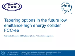
/
Tapering options in the future low Tapering options in the future low

Tapering options in the future low - PowerPoint Presentation

kittie-lecroy
kittie-lecroy . @kittie-lecroy
Follow
408 views
Uploaded On 2017-06-12

Tapering options in the future low - PPT Presentation

emittance high energy collider FCC ee Andreas Doblhammer CERN Geneva for the FCC ee lattice design team SawtoothEffect 2 Energy loss through synchrotron radiation and energy gain in RF cavities leads to characteristic ID: 558638

energy tapering sections orbit tapering energy orbit sections fcc lattice gev 175 rfs numerical kickers loss effect sawtooth lattices

Share:

Link:

Embed:

Download Presentation from below link

Download Presentation The PPT/PDF document "Tapering options in the future low" is the property of its rightful owner. Permission is granted to download and print the materials on this web site for personal, non-commercial use only, and to display it on your personal computer provided you do not modify the materials and that you retain all copyright notices contained in the materials. By downloading content from our website, you accept the terms of this agreement.


Presentation Transcript

Slide1

Tapering options in the future low emittance high energy collider FCC-ee

Andreas

Doblhammer

(CERN, Geneva)

for the FCC-

ee

lattice design teamSlide2

Sawtooth-Effect

2

Energy loss through synchrotron radiation and energy gain in RF cavities leads to characteristic “

Sawtooth

-Effect”Slide3

Energy

Dependent

Bending

Angle

3Slide4

Energy

Dependent

Bending

Angle

4

Normally the

s

awtooth

-effect would just be accepted, but in FCC-

ee

, the

sawtooth

orbit is in the mm-range

feeddown

-effect of

sextupoles

and

quadrupoles

creates additional magnetic fields that distort the opticsSlide5

What

is

Tapering

?

5

Tapering: Adjusting the strength of each

magnet so that the beam with local energy of E

0

+∆

E is on the design orbit

Of course tapering every magnet in the ring is both expensive and difficult to maintainSlide6

Analytical

Tapering

6Slide7

Numerical

Tapering

7Slide8

The

Lattices

8

FCC-

ee

12-fold

Circumference: 100 km

Energy: 175

GeV

Energy Loss/Turn ≈ 8046

M

eV

12 RF Sections (L= 1.8 km)

12 Arcs (L= 6.8 km)

Slide9

The

Lattices

9

FCC-

ee

Racetrack

Circumference: 100 km

Energy: 175

GeV

Energy Loss/Turn ≈ 7870

M

eV

4 Short Arcs (L= 4,4 km)

4 Long Arcs (L= 16,4 km)

6 Short RF Sections (L= 1,4 km)

2 RF Section (L= 4,2 km)

Slide10

The

Lattices

10

FODO-

design

Cell Length: 50 m

ε

x

≈ 1 nm*rad

Slide11

Racetrack

Lattice

, 8 RF

Sections

11

analytical Tapering

numerical TaperingSlide12

Racetrack

Lattice

, 2 RF

Sections

12

numerical Tapering

analytical TaperingSlide13

8 vs. 2 RF

sections

13

Slide14

Kicker

Strengths

&

Emittances

14

Magnet:

B*l

(Tm):

Arc Dipole

5.56*10

-1

Kicker (175

GeV

,

8RFs)

7.82*10

-4

Kicker (175

GeV

, 2RFs)

6.42*10

-3

e.g.: for a length of 0.2m,

B

k

ick

≈ 0.07*

B

dipole

for 8 RFs and ≈ 0.57*

B

d

ipole

for 2 RFs

Lattice:

ε

x

before

tapering (nm*rad)

:

ε

x

a

fter tapering (nm*rad):

8 RFs

0.9263

0.9512

2 RFs

0.9269

0.9728Slide15

Summary &

Conclusions

15

Several Tapering Methods possible

Orbit improvement through dipole tapering with kickers: ≈ Factor 50-80

Integrated strengths of the tapering kickers are ≤ 1% of the integrated strengths of the arc dipoles

Emittances

are nearly unaffected by the tapering process

Next Steps: Checking the effects of the kicker magnets

on orbit

tolerances

, using orbit correction kickers for taperingSlide16

Thank you for your attention!