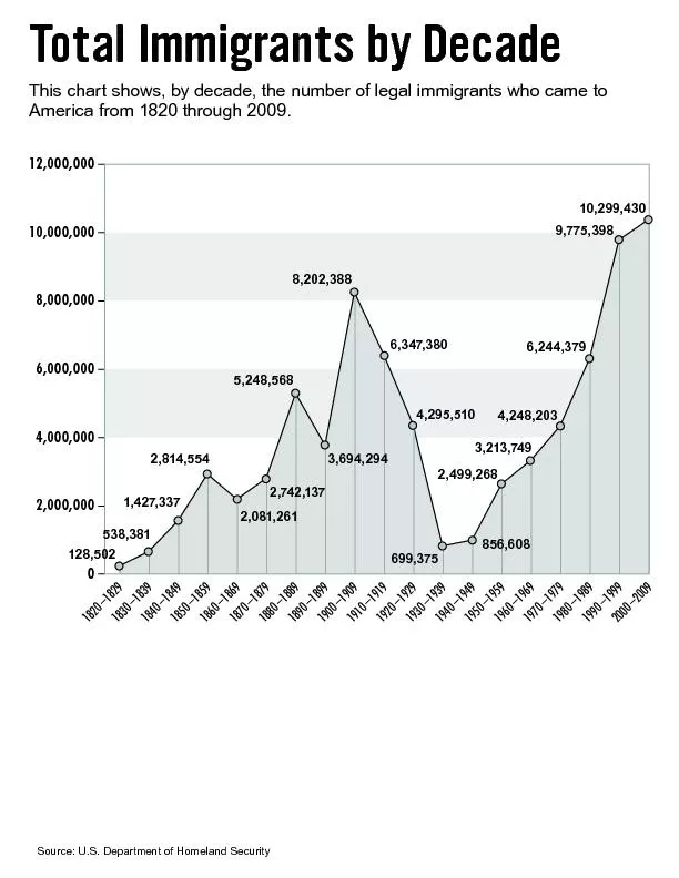
/
Understanding Mixers –  Terms Defined, and Measuring Performance Understanding Mixers –  Terms Defined, and Measuring Performance

Understanding Mixers – Terms Defined, and Measuring Performance - PDF document

kittie-lecroy
kittie-lecroy . @kittie-lecroy
Follow
396 views
Uploaded On 2015-09-07

Understanding Mixers – Terms Defined, and Measuring Performance - PPT Presentation

Todays stringent demands for precise electronic systems place a heavy burden on circuit and systems design engineers To provides the most comprehensive database components with computerautomated p ID: 123860

Today's stringent demands for precise

Share:

Link:

Embed:

Download Presentation from below link

Download Pdf The PPT/PDF document "Understanding Mixers – Terms Defin..." is the property of its rightful owner. Permission is granted to download and print the materials on this web site for personal, non-commercial use only, and to display it on your personal computer provided you do not modify the materials and that you retain all copyright notices contained in the materials. By downloading content from our website, you accept the terms of this agreement.


Presentation Transcript

Understanding Mixers – Terms Defined, and Measuring Performance Today's stringent demands for precise electronic systems place a heavy burden on circuit and systems design engineers. To provides the most comprehensive database components with computer-automated performance data and specification charts. This test modern automateequipment. Conversion loss specifications, as(mean) and sigma (standard deviation) values. A mixer is used to provide frequency translation from the input signal to the output output is the IF; for up-conversion the opposite is true. To simplify this application Conversion loss is a measure of the efficiency of the mitranslation from the RF input signal to the IF output signal. For given RF and LO frequencies, two nominally equal-amplitude output signals are produced at the sum and s. Since only one of these products (or sidebands) is utilized in most applications, thConversion loss of a mixer is equal to the ratio of the RF input power to the IF single-sideband output power, expressed as a positivebased on a 50-ohm system, with local oscillator level as specified for the pertinent mixer type. For example: for a Level 7 mixer it is +7 dBm; for Level 17, +17 dBm; and for on loss will change slightly. AN-00-009 Rev.: A M150261 (04/14/15) File: AN00009.doc This document and its contents are the property of Mini-Circuits. A Mini-Circuits active mixer has an internal amplifier in one or more of the three signal or IF path, it generally provides IF output power of conversion loss; it is equal to the ratio of the IF single-sideband output power to the as a positive number in dB. Conversion compression is a measure of the maximum RF input signal for which the mixer will provide linear operation in terms of constant conversion loss. At low RF power is within about 10 dB no longer follows the increase in RF input exactly and the ratio between IF and RF power be a greater change in the ratio, with on from linearity between the RF input power and the IF output is a fixed amount of compreRF input power at the 1-dB compression point, where conversion loss is 1 dB greater Naturally, if an application allows a greater amount of compression, the acceptable RF input power would be higher. Since the compression point changes with LO drive level, it is important to select a mixer having LO drive level that affords the required compression point for the application. The importance of this performance measure is its utility in comparing dynamic range in terms of maximum input for various mixers. Conversion compression also provides an indication of the mixer two-tone distortion performance, to be discussed later. Isolation is a measure of the circuit balance within the mixer. When the isolation is high, the amount of "leakage" or "feed through" between the mixer ports Typically, mixer isolation falls off withtransformer, lead inductance, and capacitithe highest frequency of operation, Mini-Circuits double-balanced mixers provide AN-00-009 Rev.: A M150261 (04/14/15) File: AN00009.doc This document and its contents are the property of Mini-Circuits. The LO-to-RF isolation is the amount the LOmeasured at the RF port, the IF port being terminated with 50 ohms. The LO-to-IF isolation is the amount the LO drive power port, the RF port being terminated with 50 ohms. Normally, only the LO isolations are specified, not RF isolation. This is because the RF signal power is much lower than the LO drive level; therefore, RF leakage is usually not a limiting performance factor. Dynamic range is the signal power range over which a mixer provides useful operation. s the upper limit of the dynamic range. The noise figure of the mixer signifies the lower limit of the dynamic range. Since the mixer’s noise figure is only about 0.5 dB higher than its conversion loss, the lowest conversion loss is desirable to obtain the largest dynamic range. This characteristic applies to mixers having IF response down to DC. DC polarity defines the polarity of the IF output voltage when the mixer is used as a phase detector, When the data sheet does not specify polarity for the mixer, please consult the factory. DC offset is a measure of the unbalance of thmixer, the DC offset is zero.put voltage when the mixer is terminated in 50 ohms. Two-tone third-order intesimultaneously enter the mixer RF port and interact. In practice, this could occur in a multiple-carrier signal environment, or when an undesired signal interferes with a to which the mixer generates intermodulation distortion due to its conversion-loss non-linearity. The products resulting from the interaction may be objectionable whenThe third-order spectral components at the frequency terms: |(2 |, represent the two RF input tones and fplies to down-conversion; place it with “+”. Intermodulation level is discussed in the AN-00-009 Rev.: A M150261 (04/14/15) File: AN00009.doc This document and its contents are the property of Mini-Circuits. A popular method of describing the capability of a mixer to suppress two-tone, third-order intermodulation distortion is the "third-order intercept" apprtion on the IF output versus RF input curve (each one) become equal in power, as RF input TYPICAL 2-TONE 3rd-ORDERINPUT INTERCEPT POINT, +16dBm-140-120-100-80-60-40-20-80-60-40-2002040RF INPUT POWER, EACH TONE, dBm DESIRED IF OUTPUT 3rd ORDER IM OUTPUT -17 - (-69) = 52dB suppressionIM3 Level = -52dBc -72dBc -92dBc 1 2 odulation Intercept determination, AN-00-009 Rev.: A M150261 (04/14/15) File: AN00009.doc This document and its contents are the property of Mini-Circuits. A convenient way to introduce the IP3 concept is to describe how intermodulation red output signal level. In the example of Fig. 1, -10 dBm RF input produces -17 dBm IF output (Point 1 ondB. The third-order intermodulation (IM3) power is -69 dBm, and is called the third-order suppression. We say that the mixer suppresses the third-order which means it is 52 dB below the “carrier” put). Whichever way IM3 is expressed, it is important to state along with it the corresponding RF input power, in this case -10 dBm. factor of three, or 30 dB. The difference e IM3 would increase by 20 dB; thus, the mixer would ls at its input. With another 10-dB drop in RF input to -30 dBm (Point 3 in Fig. 1), third-order products would drop another 30 e two -30 dBm input signals When will the desired IF output and the third-order products theoretically become equal? The original input signals were -10 dBm (Point 1 in Fig. 1); the output signals were -17 dBm and the third-order products werenow raised 26 dB to +16 dBm, the theoretidBm – 7dB (the conversion loss) = +9 dBm. 26 = 78 dB, making them (-69 dBm + 78 dB) = +9 dBm. Since the conversion loss is 7 dB, referencing the third-order-product power to the input of the mixer yields 9 + 7 = +16 dBm, thus establishing the Input Third-Order d signals and the third-order products are curve (past the 1-dB compression point) and thThe formula for calculating the intercept pointfference in dB between the intermodulation level at the output and the desired IF output), is: IP3 (dBm) = |IM3 - P (dBm) To refer IP3 to the input of the mixer, AN-00-009 Rev.: A M150261 (04/14/15) File: AN00009.doc This document and its contents are the property of Mini-Circuits. A rule-of-thumb method for determining the intermodulation level of a mixer is as (1) Find the 1-dB compression level (this is the RF input power level that causes the (2) Determine the intercept point. For diode mixers, at the low end of the frequency 15 dB above the 1-dB compression point. As the mid- to tercept point drops to about 10 dB above the 1-dB compression point. For FET mixers(3) Multiply the difference between the inter(equal RF tones) by the sum of the harm(4) Subtract this number from the intercept point. This yields the intermodulation level in dBm. For example, given the following conditions for a diode mixer: RF input of +1 dBm. RF input level -10 dBm, RF at low end of the mixer’s frequency range. What is third-order intermodulation power? Compression point is +1 dBm. (2) Intercept point equals 1 dBm + 15 dB = +16 dBm. (3) +16 dBm – (10 dBm) equals +26 dB. 26 dB times 3 (for third-order) = +78 dB. (4) Intermodulation power equals +16 dBm 78 dB = -62 dBm, referred to the input. conversion loss: -62 – 7 = -69 dBm. This is the example illustrated at Point 1in Fig. 1. AN-00-009 Rev.: A M150261 (04/14/15) File: AN00009.doc This document and its contents are the property of Mini-Circuits. We indicated above that a mixer’s intercept point could be estimated from its 1-dB conversion compression point. Fig. 2 illustrates the rule-of-thumb for this. For diode mixers the 15-dB value applies at low frequencies and the 10-dB value at high frequencies. For FET mixers Figure 2 The 1-dB compression point is an indication of a mixer's dynamic range AN-00-009 Rev.: A M150261 (04/14/15) File: AN00009.doc This document and its contents are the property of Mini-Circuits. Mini-Circuits policy for product measurement and preparation of specifications is sign engineer can evalhis or her circuit and system requirements and arrive at a proper design decision. For mixers, which involve control of 3 signals atparticular care is necessary. A 50-ohm broadband system is used for all factory measurements on mixers. This uniformity offers the customer a convenient and consistent means to obtain correlation by Mini-Circuits. Figure 3 presents conceptual block diagrams of test setups for measuring the performance of Level 7 mixers. In actual practice, both for sting, highly integrated and automated equipment is used to perform the m Figure 3 Test measurement setups for (a) conversion loss, (b) isolation, (c) VSWR and (d) two-tone, third-order distortion. AN-00-009 Rev.: A M150261 (04/14/15) File: AN00009.doc This document and its contents are the property of Mini-Circuits. Conversion loss measurements all three ports so the mixer sees 50 ohms at harmonics. For the IF power measurement, a low-pass filter is included before the power meter, to For example, any LO leakage has no effect does not reach the power meter. If a e power meter, the filter can be omitted. When measuring LO-RF and LO-IF isolation a pad is placed between the generator and mixer in Figure 3 (b) to ensure a 50-ohm-impedance. Also, a 50-ohm termination is e power at the RF port, and vice versa. When measuring isolation from RF-to-IF, normal LO drive and RF power in the linear alyzer replaces the RF voltmeter. This technique ensures measurement integrity: measurement is distinguishable from other components in the spectrum. For broadband applications, the effects of harmonics can only the fundamental need be considered. VSWR measurements are made under the same dynamic conditions that the mixer t, let's consider VSWR measurement at the rt and the unused IF port is terminated in 50 ohms. The RF generator supplies an ing to linear mixer operation. With the mixer disconnected from). The amount of reflected signal depends on the directional coupler used; a 20-dB coupler would establish a below the RF input. Next, the mixer is ccoupler. The spectrum analyzer acts as ected back from the mixer is displayed and scale on the spectrum analyzer. AN-00-009 Rev.: A M150261 (04/14/15) File: AN00009.doc This document and its contents are the property of Mini-Circuits. The VSWR at the IF port is meterminated in 50 ohms. VSWR at the LO port is measured with specified LO power applied (+7 dBm, in the example) via the directional coupler, and both the RF and IF ports are terminated in 50 ohms; not shown in Figure 3 (c). Broadband mixers, it should be noted, exhibdifferent frequencies. Factors causing this include circuit resonances and changes in diode impedances as the LO power level changes. Also of importance is the fact that the input impedances of the various ports isolated from each other. At high frequencies this effect is more noticeable, because isolation tends to drop as frequency increases. Two-tone, third-order intermodulation measurements Two-tone, third-order intermodulation distortion takes place when two incoming signals arrive at the mixer RF port and interact Figure 3 (d). High isolation and low harmonic content in the two RF sources are For details regarding interm“Improve Two-tone, Third Order Testing”. AN-00-009 Rev.: A M150261 (04/14/15) File: AN00009.doc This document and its contents are the property of Mini-Circuits. AN-00-009 Rev.: A M150261 (04/14/15) File: AN00009.doc This document and its contents are the property of Mini-Circuits. © 2015 Mini-Circuits This document is provided as an accommodation to Mini-Circuits customers in connection with Mini-Circuits parts only. In that regard, this document is for informational Mini-Circuits assumes no responsibility for errors or omissions in this document or for any information contained herein. Mini-Circuits may change this document or the Mini-Circuits parts referenced herein (collectively, the “Materials”) from time to time, without notice. Mini-Circuits makes no of the Materials, and Mini-Circuits shall have no responsibility whatsoever on account of any updates or corrections to the Materials or Mini-Circuits’ failure to do so. Mini-Circuits customers are solely responsible for the products, systems, and applications in which Mini-Circuits parts are incorporated or used. In that regard, customers r own engineers and other appropriate professionals who are familiar with the specific products and systems into which Mini-Circuits’ parts are to be incorporated or used so that the proper selection, installation/integration, use and safeguards are made. Accordingly, Mini-Circuits assumes no liability therefor. In addition, your use of this document and the information contained herein is subject to Mini-Circuits’ standard terms of use, which are available at Mini-Circuits’ website at www.minicircuits.com/ Mini-Circuits and the Mini-Circuits logo are registered trademarks of Scientific Components Corporation d/b/a Mini-Circuits. All other third-party trademarks are the property of their respective owners. A reference to any third-party trademark does not constitute or imply any endorsement, affiliation, sponsorship, or recommendation: (i) by Mini-Circuits of such third-party’s products, services, processes, or other information; or (ii) by any such third-party of Mini-Circuits or its products, services, processes, or other information.