/
Imaging Methods to Evaluate Spine Imaging Methods to Evaluate Spine

Imaging Methods to Evaluate Spine - PowerPoint Presentation

kylie
kylie . @kylie
Follow
27 views
Uploaded On 2024-02-09

Imaging Methods to Evaluate Spine - PPT Presentation

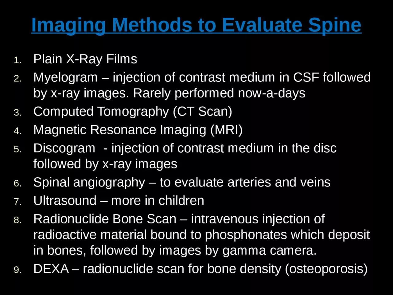
Plain XRay Films Myelogram injection of contrast medium in CSF followed by xray images Rarely performed nowadays Computed Tomography CT Scan Magnetic Resonance Imaging MRI Discogram injection of contrast medium in the disc followed by xray images ID: 1045048

mri spinal contrast imaging spinal mri imaging contrast disc images vertebral anterior bone cord scan shows soft ray injected

Share:

Link:

Embed:

Download Presentation from below link

Download Presentation The PPT/PDF document "Imaging Methods to Evaluate Spine" is the property of its rightful owner. Permission is granted to download and print the materials on this web site for personal, non-commercial use only, and to display it on your personal computer provided you do not modify the materials and that you retain all copyright notices contained in the materials. By downloading content from our website, you accept the terms of this agreement.


Presentation Transcript

1. Imaging Methods to Evaluate SpinePlain X-Ray FilmsMyelogram – injection of contrast medium in CSF followed by x-ray images. Rarely performed now-a-daysComputed Tomography (CT Scan) Magnetic Resonance Imaging (MRI)Discogram - injection of contrast medium in the disc followed by x-ray images Spinal angiography – to evaluate arteries and veinsUltrasound – more in childrenRadionuclide Bone Scan – intravenous injection of radioactive material bound to phosphonates which deposit in bones, followed by images by gamma camera. DEXA – radionuclide scan for bone density (osteoporosis)

2. X-RAYS (RADIOGRAPHS)Often the first diagnostic imaging test, quick and cheapSmall dose of radiation to visualize the bony parts of the spineCan detect Spinal alignment and curvature Spinal instability – with flexion and extension views Congenital (birth) defects of spinal column Fractures caused by trauma Moderate osteoporosis (loss of calcium from the bone) Infections Tumors May be taken in different positions (ie; bending forward and backward) to assess for instability

3. COMPUTERIZED TOMOGRAPHY (CT SCAN)Uses radiation to obtain 2-D and 3-D imagesPatients must lie still on a table that moves through a scannerCross-sectional images are obtained of the target areasMuch detailed information regarding bony and soft tissuesBetter in visualizing Degenerative or aging changes, Herniated discs Spinal alignment Fractures and fracture patterns Congenital / childhood anomalies Areas of narrowing in spinal canal through which spinal cord and spinal nerve roots passPoor in visualizing inner details of spinal cordEntire spine can be imaged within a few minutesA contrast material may be injected intravenously or intrathecally to make some areas clear

4.

5.

6. MYELOGRAMA contrast material is injected into CSF to better identify areas where spinal cord or spinal nerves may be compressedPROCEDURE:Under local anesthesia, a needle is placed into lower lumbar spinal canal, and then CSF flow is confirmed. Contrast medium is then injected which mixes with CSF around spinal cord, making it visible on x-ray images Often a CT scan is also performed after thisMay be performed when MRI is contraindicated

7. Magnetic Resonance Imaging (MRI)The gold standard of imaging for spinal disordersDoes not use ionizing radiationCan identify abnormalities of bone, discs, muscles, ligaments and spinal cordIntravenous contrast is sometimes administered to better visualize certain structures or abnormalitiesPatient lies still in a tunnel like structure for about 25 minutesClaustrophobic patients may need sedation, and children often need general anesthesia Contraindications include Implanted devices e.g. cardiac pacemakers Artificial joints and spinal hardware may still have MRI scans

8. MRI SCANNER (closed type)

9. MRI SCANNER (open type)

10. MR images are multi-planar

11. MR images are very high resolution

12. MR images are very high resolution

13.

14. DISCOGRAMDiscs are the cushions between the vertebral bodiesWhile MRI and CT scans can provide structural information, discogram better identifies the relationship of disc to painPROCEDURE: A needle is placed into center of the disc under fluoroscopy (continuous x-ray imaging) A contrast material (dye) is injected Radiologist then observes if patient experiences pain that is similar to his/her usual pain, and is increased by injecting contrastX-rays (+ CT scan) are then done to see if dye stays within the center of the disc or leaks to outer border of the disc indicating a tear in annulus fibrosus of disc which can be a source of pain

15. Congenital Anomalies

16. CONGENITAL ANOMALIESSkin covered defects and Open skin defectsMRI is the best to assess the contents of the cavity, extent of abnormalities, and spinal cord.CT shows bony structures the best and is often used before surgery

17. Multiple fusion abnormalities of vertebrae on plain film

18. TRAUMA

19. Plain film assessment of trauma – the first imaging method

20. Alignment should be normal – check by drawing lines

21.

22.

23. Soft tissue anterior to spine is very important

24. Jefferson FractureLateral displacement of C1 in plain film (A)Coronal reconstruction from a CT confirms the findings from the odontoid viewAxial CT clearly shows the location of the fractures of C1

25.

26.

27. Hangman's FractureFractures through the pars interaticularis of C2 resulting from hyperextension and distractionHyperextension (e.g. hanging, chin hits dashboard in road accident)Radiographic features: (best seen on lateral view) 1. Prevertebral soft tissue swelling2. Avulsion of anterior inferior corner of C2 associated with rupture of anterior longitudinal ligament. 3. Anterior dislocation of C2 vertebral body4. Bilateral C2 pars interarticularis fractures

28. Bilateral Facet DislocationComplete anterior dislocation of vertebral body resulting from extreme hyperflexion injuryAssociated with a very high risk of cord damage

29. Unilateral Facet DislocationFacet joint dislocation and rupture of the apophyseal joint ligaments resulting from rotatory injuryMechanism: simultaneous flexion and rotation

30. Burst FractureResults from axial compressionInjury to spinal cord is common due to displacement of posterior fragmentsCT is required for all patient to evaluate extent of injury

31. INFECTIONS

32. Usually the result of blood–borne agents Especially from lung and urinary tract Most common pathogen is staphylococcus, Streptococcus less commonGram-negative rods in IV drug abusers or immunocompromised patients E. Coli Proteus Non-pyogenic Tuberculosis Coccidioidomycosis May occur after invasive procedure like Surgery, Discography, Myelography In children, infection begins in vascularized disc In adults, in anterior inferior corner of vertebral body with spread across disk to adjacent vertebral endplate Site of involvement L3/4 L4/5 Unusual above T9 Usually involvement of one disk space (occasionally 2) Discitis and Osteomyelitis

33. IMAGING FINDINGSPLAIN FILMSNarrowing and destruction of an intervertebral disk Earliest plain film sign Indistinct adjacent endplates with destruction Often associated with bony sclerosis of the two contiguous vertebral bodies Paravertebral soft tissue mass Endplate sclerosis (during healing phase beginning anywhere from 8 weeks to 8 months after onset) Bone fusion after 6 months to 2 yearsMRI Bone marrow edema in infected vertebrae, discs and paraspinal soft tissues Dark on T1 and bright on T2 imagesEnhancement of inflammed tissues after contrastFluid collections (abscesses) are commonDiscitis and Osteomyelitis

34. cDiscitis and Osteomyelitis

35. A. Sagittal T1 MRI shows decreased signal of vertebral bodies and disc with end plate destructionB. Sagittal T2 MRI shows increased signal in corresponding areas with anterior subligamentous abscess, epidural involvement and extension of inflammation in T6 with preserved endplateC. Axial contrast-enhanced T1 MRI shows peripheral enhancement of paravertebral abscess and marked enhancement of epidural tissues causing displacement of spinal cordD. CT shows lytic lesion in vertebral body and paravertebral abscess with calcifications

36. TUMORS

37.

38. AJNR

39.

40.

41. THANKS