/
Electronic Journal of Structural Engineering, 4 (2004)  2001 EJSE Inte Electronic Journal of Structural Engineering, 4 (2004)  2001 EJSE Inte

Electronic Journal of Structural Engineering, 4 (2004) 2001 EJSE Inte - PDF document

lindy-dunigan
lindy-dunigan . @lindy-dunigan
Follow
406 views
Uploaded On 2015-10-12

Electronic Journal of Structural Engineering, 4 (2004) 2001 EJSE Inte - PPT Presentation

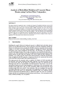
eJJSSEE International Analysis of Retrofitted Reinforced Concrete Shear RSanthakumar and EChandrasekaran Dept of Civil Engg Crescent Engg College IndiaDeptof Aeronautical Engg MIT Anna Unive ID: 158292

eJJSSEE International Analysis Retrofitted Reinforced

Share:

Link:

Embed:

Download Presentation from below link

Download Pdf The PPT/PDF document "Electronic Journal of Structural Enginee..." is the property of its rightful owner. Permission is granted to download and print the materials on this web site for personal, non-commercial use only, and to display it on your personal computer provided you do not modify the materials and that you retain all copyright notices contained in the materials. By downloading content from our website, you accept the terms of this agreement.


Presentation Transcript

Electronic Journal of Structural Engineering, 4 (2004) 2001 EJSE International. All rights reserved. Website: http://www.ejse.org eJJSSEE International Analysis of Retrofitted Reinforced Concrete Shear R.Santhakumar and E.Chandrasekaran Dept. of Civil Engg. Crescent Engg. College, IndiaDept.of Aeronautical Engg. MIT, Anna University, India. ABSTRACT This paper presents the numerical study to simulate the behavior of retrofitted reinforced concrete (RC) shear beams. The study was carried out on the unretrofitted RC beam designated as control beam and RC beams retrofitted using carbon fiber reinforced plastic (CFRP) composites with ±45 and 90 fiber orientations. The effect of retrofitting on uncracked and precracked beams was studied too. The finite Modelling the complex behavior of reinforced concrete is a difficult task in the finite element analysis of civil engineering structures. Only recently have researchers attempted to simulate the behavior of reinforced concrete strengthened with FRP composites using finite element method. Arduini, et al. (1997) used finite element method to simulate the behavior and failure mechanisms of RC beams strengthened with FRP plates. The FRP plates were modeled with Electronic Journal of Structural Engineering, 4 (2004) 2001 EJSE International. All rights reserved. Website: http://www.ejse.org eJJSSEE International 2 Geometry and material properties The geometry and the material properties as reported by Tom Norris, et al. (1997) were used for this study. The control beam dimensions along with the reinforcement details are shown in figure-1. Figure 1: Details of control beam The average yield stress of rebar and the compressive strength of concrete were reported as 420 MPa (61000 psi) and 36.5 MPa (5300 psi) respectively (4). The Young’s modulus and tensile strength of the concrete were calculated as 30186 MPa (4383.17 ksi) and 2.174 MPa (0.3156 ksi) respectively (5,6). Poison’s ratio was assumed as 0.2 for concrete and 0.3 for steel rebar. The shear transfer coefficient for open crack and closed crack were considered as 0.2 and 0.22 respectively (3). The elastic modulus of steel rebar was taken as 200000 MPa (29000 ksi). The summary of the properties of CFRP composites as reported by Tom Norris, et al. (1997) are shown in Table –1. CFRP system Number of layers Thickness (inches) Tensile strength MPa (ksi) Longitudinal modulus GPa (ksi) Transverse modulus GPa (ksi) Shear modulus GPa (ksi) Poison’s ratio fiber orientation One fiber orientation Two Table 1: Material properties of CFRP composites 3 Numerical study Finite elements The finite elements adopted by ANSYS were used (7). Solid 65 elements were used to model the concrete. The rebar capability of this model was not considered. All reinforcements were modeled using Link 8- 3D spar element. Solid 45 elements were used for the steel plates at the support and under the load. A layered solid element, solid 46 was used to model the CFRP composites. Modeling of reinforced concrete control beam Electronic Journal of Structural Engineering, 4 (2004) 2001 EJSE International. All rights reserved. Website: http://www.ejse.org eJJSSEE International A quarter of the full beam was used for modeling by taking advantage of the symmetry of the beam and loadings. Planes of symmetry were required at the internal faces. At a plane of symmetry, the displacement in the direction perpendicular to that plane was held at zero. The displacements in the plane of loading were achieved by providing rollers along the axes of symmetry. A convergence study on quarter model of the full plain concrete beam without steel reinforcements was carried out to determine an appropriate mesh density. The convergence of results is obtained when an adequate number of elements are used in a model. This is practically achieved when an increase in the mesh has negligible effect on the results (8). The plain concrete beams of same material properties were modeled with an increasing number of elements 432, 744, 912, 1008, 1104, 1200, 1296, 1580 and 1824. The mid span deflection for all beams was observed for the same applied load of 0.4 kips. Figure-2. Shows the result of the convergence study on mid span deflection. 0.00290.002970.003040.003110.003180.003250500100015002000No of ElementsMid span deflection (inches)0.073660.075660.077660.079660.08166Mid span deflection (mm) Figure 2: Plot for convergence studyFrom the graph it was found that models with number of elements more than 1296 had negligible effect on mid span deflection. So the finite element model consisting of 1440 number of solid 65 concrete elements was used for this entire study. A finer mesh was provided near the loading locations and mid span. The bond between steel reinforcement and concrete was assumed as perfect and no loss of bond between them was considered in this study (3,9). The link 8- 3D spar element for the steel reinforcement was connected between nodes of each adjacent concrete solid 65 elements. Figure –3 shows a typical quarter symmetry finite element model for the control beam. Electronic Journal of Structural Engineering, 4 (2004) 2001 EJSE International. All rights reserved. Website: http://www.ejse.org eJJSSEE International Figure 3: Quarter symmetry finite element model of control beam Modelling of retrofitted beam In the retrofitted beam the layered solid 46 elements used to represent the CFRP composites were attached to the finite element model of control beam as shown in figure-4. (a) Beam wrapped with CFRP composite (b) Finite element model Figure 4: Retrofitted beam To simulate the perfect bonding of the CFRP sheets with concrete the nodes of solid 46 elements were connected to the nodes of solid 65 elements at the interface so that two materials shared the same nodes. For the beam retrofitted using CFRP composites with 90 fiber orientation the thickness of the solid 46 elements was doubled due to geometric constraints from the other concrete elements in the model. However the equivalent overall stiffness of the solid 46 elements was maintained by making changes in the elastic and shear moduli (3). Modelling of precracked retrofitted beam Electronic Journal of Structural Engineering, 4 (2004) 2001 EJSE International. All rights reserved. Website: http://www.ejse.org eJJSSEE International Generally, in precracked retrofitted beam the CFRP composites were bonded to the concrete beam after cracking of concrete. However, in this study, for the ease of modeling the solid 46 elements were attached to the basic concrete model prior to cracking of concrete, but were assigned with the material property of concrete. It was assumed that this addition of thin layer of solid 46 elements assigned with concrete material property would have negligible effect in the behavior of uncracked concrete beam. The retrofitted beam model in this status was loaded up to the stage of cracking of concrete. After cracking of concrete, the material properties of solid 46 elements were updated with the properties of CFRP composites for further loading up to 3.1 Non-linear solution and failure criteria In this study the total load applied was divided in to a series of load increments (or) load steps. Newton –Raphson equilibrium iterations provide convergence at the end of each load increment within tolerance limits. The automatic time stepping in the ANSYS program predicts and controls load step sizes for which the maximum and minimum load step sizes are required (7). After attempting many trials the number of load steps, minimum and maximum step sizes were determined. During concrete cracking, steel yielding and ultimate stage in which large numbers of cracks occur the loads were applied gradually with smaller load increments. Failure for each model was identified when the solution for 0.009kN (0.002kips) load increment was not converging. 4 Results and discussion Comparison of load versus mid span deflection plots The load versus mid span deflection plots for beams C48, IIIFu and IE obtained from numerical study along with the experimental plots reported by Tom Norris, et. al (1997) are presented and compared in figures - 5(a) and 5(b). When comparing with the experimental values, the numerical models show 8% increase in ultimate load for control beam (C48) and uncracked retrofitted beam (IIIFu) and 8% decrease in ultimate load for precracked retrofitted beam (IE). At the ultimate stage all the numerical models show less deflection, especially the precracked retrofitted beam shows 31% less In numerical analysis the compressive uniaxial stress – strain relationship for concrete is required for defining the material nonlinearity (7). However, in this study, the Young’s modulus for concrete was considered as a constant for all ranges of loading, since the stress –strain history was not reported by Tom Norris, et. al. All numerical plots in this study show almost linear response with higher stiffness when compared with the experimental plots. Electronic Journal of Structural Engineering, 4 (2004) 2001 EJSE International. All rights reserved. Website: http://www.ejse.org eJJSSEE International 100150200051015202530Deflection (mm)Load (kN)00.20.40.60.811.2Deflection (inches)Load (kips) Experimental umerical Control beamControl beamRetrofitted beamRetrofitted beam5(a). Uncracked retrofitted beam 100150200051015202530Deflection (mm)Load (kN)00.20.40.60.811.2Deflection (inches)Load (kips) Experimental umerical Control beamControl beamRetrofitted bea m Retrofitted beam 5(b). Precracked retrofitted beam Figure 5: Comparison of load versus mid span deflection plots Effect of retrofitting on precracked and uncracked beams Figure -6. shows the load versus mid span deflection plots from the numerical analyses for precracked and uncracked beams retrofitted using CFRP composites with 90o fiber orientation. Electronic Journal of Structural Engineering, 4 (2004) 2001 EJSE International. All rights reserved. Website: http://www.ejse.org eJJSSEE International 00.20.40.60.811.2Deflection (inches)Load (kips)100150200051015202530Deflection (mm)Load (kN)1.Uncracked retrofitted beam 2.Precracked retrofitted beam Figure 6: Load deflection plots of retrofitted beams The uncracked and precracked retrofitted beams show the same stiffness up to yielding of reinforcing bars. At the ultimate stage the precracked retrofitted beam shows 6.7% decrease in Crack patterns The crack patterns in the control beam at failure obtained from numerical study and from the experimental work reported by Tom Norris, et. al are presented in figure -7(a) and 7(b), which are very similar. 7(a). Crack pattern from numerical study 7(b). Crack pattern of experimentally tested beam (Tom Noris, et. al) Figure -7. Crack patterns of control beam Figure 8 shows the crack patterns at different loadings for uncracked retrofitted beams using CFRP composites with ± 45 Electronic Journal of Structural Engineering, 4 (2004) 2001 EJSE International. All rights reserved. Website: http://www.ejse.org eJJSSEE International Crack pattern at 11.16 kN (2.51 kips) Crack pattern at 66.75 kN (15 kips) Figure 8. Crack patterns of uncracked retrofitted beam Flexural cracks occurred early near the mid span. These cracks were followed by diagonal shear cracks near the support and compressive cracks under the load at higher loads. 5 Conclusions A numerical study is carried out for retrofitted reinforced concrete shear beams using the finite elements adopted by ANSYS. The numerical results show good agreement with the experimental values reported by Tom Noris et. al.. At ultimate stage there is a difference in behavior between the uncracked and precracked retrofitted beams though not significant. This numerical modeling helps to track the crack formation and propagation especially in case of retrofitted beams in which the crack patterns cannot be seen by the experimental study due to wrapping of CFRP composites. This numerical study can be used to predict the behavior of retrofitted reinforced concrete beams more precisely by assigning appropriate material 6 Acknowledgements The authors sincerely thank the management authorities of Crescent Engineering College, Chennai, for their consistent support and facilities provided. The authors also wish to acknowledge the assistance of M.Karthick in the preparation of this paper. 1. Arduini,M., Di Tommaso,A., and Nanni,A., ‘Brittle Failure in FRP Plate and Sheet Bonded Beams’, ACI Structural Journal, 94 (4), pp.363-370, 1997. Electronic Journal of Structural Engineering, 4 (2004) 2001 EJSE International. All rights reserved. Website: http://www.ejse.org eJJSSEE International 2. Tedesco,J.W., Stallings J.M., and El-Mihilmy, M., ‘Finite Element Method Analysis of a Concrete Bridge Repaired with Fiber Reinforced Plastic Laminates’, Computers and Structures, 72, 379-407, 1999. 3. Kachlakev Damian, Miller Thomas, and Yim Solomon, ‘Finite Element Modeling of Reinforced Concrete Structures Strengthened with FRP Laminates’ Report for Oregon Department Of Transportation, Salem, May 2001. 4. Norris Tom, Saadatmanesh Hamid and Ehsani Mohammad R., ‘Shear and Flexural Strengthening of R/C Beams with Carbon Fiber Sheets’, Journal of Structural Engineering, vol.123, no.7, July, 1997. 5. Hughes,B.P., Limit State Theory for Reinforced Concrete Design, 1976, 2 edition, Pitman Publishing Ltd (London). 6. BS 8110, Structural use of concrete, part 1, 1985, British Standards Institution, London. 7. ANSYS, ANSYS User’s Manual. 8. Adams,V. and Askenazi, A., ‘Building better products with Finite Element Analysis’, On 9. Fanning, P. ‘Nonlinear Models of Reinforced and Post-tensioned concrete beams’, Electronic Journal of Structural Engineering, 2 (2001).