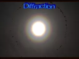
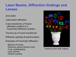
Zone plate Laserbeam diffraction A lens transforms a Fresnel diffraction problem to a Fraunhofer diffraction problem The lens as a Fourier transformer Diffraction gratings amp spectrometers ID: 615180
Download Presentation The PPT/PDF document "Laser Beams, Diffraction Gratings and Le..." is the property of its rightful owner. Permission is granted to download and print the materials on this web site for personal, non-commercial use only, and to display it on your personal computer provided you do not modify the materials and that you retain all copyright notices contained in the materials. By downloading content from our website, you accept the terms of this agreement.
Slide1
Laser Beams, Diffraction Gratings and Lenses
Zone plateLaser-beam diffractionA lens transforms a Fresnel diffraction problem to a Fraunhofer diffraction problem.The lens as a Fourier transformerDiffraction gratings & spectrometersExamples of Fraunhofer diffraction: Babinet’s Principle Randomly placed identical holes X-ray crystallography Laser speckle Particle counting
Thanks to Prof. Rick
Trebino
, Slide2Slide3Slide4
Recall the Fraunhofer diffraction formula.
that is:
and:
E
(
x
,
y
)
= constant if a plane wave
Aperture transmission function
The far-field light field is the Fourier Transform of the apertured field.
k
x
= kx
’
/
z and ky = ky’/z
The k’s are off-axis k-vectors.Slide5
w
0
’
z
w
0
A laser beam typically has a
Gaussian radial profile:
No aperture is involved.
Fraunhofer Diffraction of a Laser Beam
The Fourier transform of a Gaussian is a Gaussian.
What will its electric field be far away?
In terms of
x
’
and
y
’
:
or
where:
The larger the beam initially, the smaller the beam far away.Slide6
The beam diverges.
What will its divergence angle be?
Angular Divergence of a Laser Beam
The half-angle will be:
The divergence half-angle will be:
Recall that:
w
0
q
z
w
0
’Slide7
Gaussian Beams
The Gaussian beam is the solution to the wave equation, or equivalently, the Fresnel integral, for a wave in free space with a Gaussian profile at z = 0.
The beam has a waist at
z = 0, where the spot size is w0. It then expands to
w = w
(
z
)
with distance
z
away from the waist.
The beam radius of curvature, R(z), is ∞ at z = 0. It then decreases but eventually increases with distance far away from the waist.
x
Collimated region
(where the spot size remains ~ constant)
R
(
z
)
= wave-front radius
of curvature
w
(
z
)
z
Beam radius
w
(
z
)
Beam waistSlide8
Gaussian Beam Expression
The expression for a real laser beam's electric field is given by:
Recall the phase factor in front of the diffraction integrals.
z
w
0
w
(
z
)
R
(
z
)
This is the solution to the wave equation or, equivalently, the Fresnel diffraction integral.
w
(
z
)
is the spot size vs. distance from the waist,
R
(
z
)
is the beam radius of curvature, and
y
(
z
)
is a phase shift.Slide9
z
w
0
w
(
z
)
R
(
z
)
z
R
Gaussian Beam Spot,
Radius, and Phase
The expressions for the spot size, radius of curvature, and phase shift:
where
z
R
is the
Rayleigh range
, and it's given by:
Twice the Rayleigh range is the distance over which the beam remains about the same size, that is, remains
collimated.Slide10
Collimation Collimation
Waist spot Distance Distance
size w0
l = 10.6 µm l = 0.633 µm.225 cm 0.003 km 0.045 km 2.25 cm 0.3 km 5 km
22.5 cm 30 km 500 km
Longer wavelengths and smaller waists expand faster than shorter ones.
As a result, it's very difficult to shoot down a missile with a laser—the beam is most intense at the laser and dims with distance.
Gaussian Beam Collimation
Tightly focused laser beams expand quickly.
Weakly focused beams expand less quickly, but still expand.
w
0Slide11
The Gouy Phase Shift
The phase factor yields a phase shift relative to the phase of aplane wave when a Gaussian beam goes through a focus.
Phase relative
to a plane wave:
Recall the
i
in front of the Fresnel integral, which is a result of the Gouy phase shift.
p/2
-p/2
z
R
-z
R
y
(
z
)
zSlide12
Laser Spatial Modes
Some Transverse Electro-Magnetic (TEM) modes
Electric field
Laser beams can have any pattern, not just a Gaussian. And the phase shift will depend on the pattern. The beam shape can even change with distance.
Some beam shapes do not change with distance. These laser beam shapes are referred to as
Transverse Electro-Magnetic (TEM) modes
. The actual field can be written as an infinite series of them.
The 00 mode is the Gaussian beam. Higher-order modes involve multiplication of a Gaussian by a
Hermite polynomial
.Slide13
Laser Spatial Modes
Some Transverse Electro-Magnetic (TEM) modes
IrradianceSlide14
Laser Spatial Modes
Some particularly pretty measured laser modes (with a little artistic license…)Slide15
d
(
x,y
)
R
Diffraction Involving a Lens
A lens has unity transmission, but it adds an extra phase delay proportion-al to its thickness at a given point
(
x,y
)
:
where
L
(
x,y
) is the thickness at (
x,y
).
neglecting constant phase delays (that are independent of
x
and
y
).
Compute
L
(
x,y
)
:
Observation plane
Lens
Object
Illumi-nation
f
f
t
object
(
x
,
y
)
t
lens
(
x
,
y
)Slide16
Recalling the Lens-maker’s formula,
z is the lens focal length!
A lens brings the far field in to its focal plane.
A lens phase delay due to its thickness at the point (x,y):
The quadratic terms inside the exponential will cancel provided that:
Substitute this result into the Fresnel (not the Fraunhofer!) integral:
QED
For a lens that's curved on both
faces, cancellation occurs if:Slide17
A lens brings the far field in to its focal length.
One focal length behind a lens is the Fraunhofer regime—even if it isn’t far away! There, we’ll see the Fourier transform of the product tobject(x,y) E(x,y)—the field immediately in front of the lens!
A lens in this configuration is said to be a
Fourier-transforming lens
.
This yields:
Observation plane
Lens
Object
Illumi-nation
f
f
t
object
(
x
,
y
)
F
{
t
object
(
x
,
y
)
E
(
x
,
y
)}
E
(
x,y
)
Fourier transform of objectSlide18
A laser beam typically has a
Gaussian radial profile:
Focusing a Laser Beam
What will its electric field be one focal length after a lens?
or
where:
Look familiar? This is the same result for a beam diffracting! Here, the beam is propagating backwards.
or:
2
w
0
f
Lens
f
2
w
0
’Slide19
Recall that we showed earlier that a beam cannot focus to a spot smaller than
l/2. But this result
How tightly can we focus a laser beam?
seems to say that, if
w
0
is huge, we can focus to an arbitrarily small spot
. What’s going on?
The discrepancy comes from our use of the
paraxial approximation
here in diffraction, where we assumed small-angle propagation with respect to the
z-axis. So don’t use this result when the focus is extremely tight! A beam cannot be focused to a spot smaller than l/2.
On the other hand, unlike geometrical optics, this formula at least tells us the correct focused spot size—except in the above limit.
2
w
0
f
f
2
w
0
’
w
0
’Slide20
A diffraction grating is a slab with a periodic modulation of any sort on one of its surfaces.
The Diffraction Grating
The grating is then said to be a transmission grating, reflection grating, or phase grating, respectively.
Diffraction gratings diffract different wavelengths into different directions, thus allowing us to measure spectra.
Diffraction angle,
q
m
(
l
)
Zeroth order
First order
Minus first order
The modulation can be in transmission, reflection,
or the
phase delay
of a beam.Slide21
Diffraction Grating Mathematics
Begin with a sinusoidal modulation of the transmission: where a is the grating spacing. The Fraunhofer diffracted field is:
Ignoring the
y
-integration, the
x
-integral is just the Fourier transform:
1
st
order
0
th
order
-1
st
order
Substituting for
k
xSlide22
Diffraction Orders
z
x
’
Because
x
’
depends on
l
, different wavelengths are separated in the nonzero orders.
No wavelength dependence in zero order.
The longer the wavelength, the larger its diffraction angle in nonzero orders.Slide23
Diffraction Grating Math: Higher Orders
What if the periodic modulation of the transmission is not sinusoidal?Since it's periodic, we can use a Fourier Series for it:
A square modulation is common. It has many orders.
Keeping up to third order, the resulting Fourier Transform is:Slide24
The Grating Equation
If we now assume normal incidence (qi = 0) and a small diffraction angle, we see that an order of a diffraction grating occurs if: where m is an integer.This is the same result we just obtained using diffraction ideas.
Scatterer
Scatterer
a
q
i
q
m
a
AB
=
a
sin(
q
m
)
CD
=
a
sin(
q
i
)
A
D
C
B
Diffracted wave-front
Incident wave-front
q
i
q
m
Recall that, using scattering ideas, we derived a more general result, the grating equation:
But scattering doesn’t provide the relative intensities of each order.Slide25
Blazed Diffraction Gratings
By tilting the facets of the grating so the desired diffraction ordercoincides with the specular reflection from the facets, the gratingefficiency of a particular order can be increased.
Specular
means angle of incidence equals angle of reflection.
Input beam
Efficient diffraction
Inefficient diffraction
Even though both diffracted beams satisfy the grating equation, one is vastly more intense than the other.
The analysis using the diffraction integral allows us to model this type of grating and determine the relative intensities of each order.
FacetSlide26
d
Diffraction-Grating Spectrometer Resolution
How accurate is a diffraction-grating spectrometer (a grating followed by a lens)?
f
Two
similar
colors
illuminate
the
grating.
f
Two nearby wavelengths will be resolvable if they’re separated by at least one spot diameter, .
The diffraction grating will separate them in angle by
dq
, which will become
f
dq
at the focal plane of the lens.
d
cos(
q
m
)
dq
2
w
0
’
2
w
0
’
For simplicity, assume normal incidence onto the grating.Slide27
Diffraction-Grating Spectrometer Resolution
Recall the grating angular dispersion:
So two nearby spots will be separated by:
where
N
= # grating lines illuminated =
d
/
a
or
d
f
dq
f
Setting this distance equal to the focused-spot diameter, :
2
w
0
’Slide28
Diffraction-Grating Spectrometer Resolution
Let’s plug in some numbers:
2
w
0
f
f
l
≈ 600nm
m
= 1
N
= (50mm) × (2400 lines/mm) = 120,000 lines
For simple order-of-magnitude estimates,
4
/
p
≈
1
:
And the resolution,
dl
/
l
, depends only on the order and how many lines are illuminated!
Resolving Power:
2
w
0
’Slide29
Holes
Anti-
Holes
The diffraction pattern of a transmission function is the same as that of its opposite!
Neglecting the center point:
Babinet’s
PrincipleSlide30
Fraunhofer Diffraction: Interesting Example
Randomly placed identical holes yield a diffraction pattern whose gross features reveal the shape of the holes.
Hole Diffraction
pattern pattern
Square holes
Round holesSlide31
The Fourier Transform of a Random
Array of Identical Tiny ObjectsDefine a random array of two-dimensional delta-functions:
Sum of rapidly
varying sinusoids(looks like noise)
Shift Theorem
Rapidly varying Slowly varying
The Fourier transform of this random array is then:
If
t
hole
(
x,y
)
is the shape of an individual tiny hole, then a random array of identically shaped tiny holes is:
where
(
x
i
,
y
i
)
are random pointsSlide32
The tendency of diffraction to expand the smallest structure into the largest pattern is the key to the technique of x-ray crystallography, in which x-rays diffract off the nuclei of crystals, and the diffraction pattern reveals the crystal molecular structure.
This works best with a single crystal, but, according to the theorem we just proved,
it also works with powder
.
X-Ray CrystallographySlide33
Laser speckle is a diffraction pattern.
When a laser illuminates a rough surface, it yields a
speckle pattern. It’s the diffraction pattern from the very complex surface. Don’t try to do this Fourier Transform at home.
Laser illumination
Incoherent illumination
Speckle
Technically, both images are diffraction patterns, but the incoherent illumination is so complex in time and space you can’t see the speckle.Slide34
Particle Detection and Measurement by DiffractionSlide35
Moon coronas are due to diffraction.
When the moon looks a bit hazy, you’re seeing a
corona
. It’s a diffraction effect.Slide36
Frontiers of Optics
Ultrafast opticsNonlinear opticsNon-diffracting beams
Ultrahigh intensity
Arbitrary-waveform generation
Ultrahigh-resolution spectroscopy
Ultracold atoms
Laser accelerators
Meta-materials
Super-resolution imagingSlide37
The vast majority of humankind’s greatest discoveries have resulted directly from light and its measurement.
Spectrometers led to quantum mechanics.
The Michelson interferometer led to relativity.
Microscopes led to biology.
Telescopes led to astronomy.
X-ray crystallography solved DNA.
And technologies, from medical imaging to GPS, result from light measurement!Slide38
With your newfound optics knowledge, perhaps you’ll make the next one.