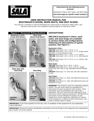
/
User instruction manual for boatswain's chairs works seats and seat slings User instruction manual for boatswain's chairs works seats and seat slings

User instruction manual for boatswain's chairs works seats and seat slings - PDF document

lindy-dunigan
lindy-dunigan . @lindy-dunigan
Follow
381 views
Uploaded On 2017-07-26

User instruction manual for boatswain's chairs works seats and seat slings - PPT Presentation

brPage 1br LQ57347YDULRXV57347VWOHV57347DQG57347FRQ57535JXUDWLRQV VVWHPV57361573476HH57347LJXUH 573475HFRUG57347WKH57347SURGXFW57347LGHQWL57535FDWLRQ5 ID: 62628

brPage 1br LQ57347YDULRXV57347VWOHV57347DQG57347FRQ57535JXUDWLRQV VVWHPV57361573476HH57347LJXUH 573475HFRUG57347WKH57347SURGXFW57347LGHQWL57535FDWLRQ5

Share:

Link:

Embed:

Download Presentation from below link

Download Pdf The PPT/PDF document "User instruction manual for boatswain's ..." is the property of its rightful owner. Permission is granted to download and print the materials on this web site for personal, non-commercial use only, and to display it on your personal computer provided you do not modify the materials and that you retain all copyright notices contained in the materials. By downloading content from our website, you accept the terms of this agreement.


Presentation Transcript

1 © Copyright 2009, DB Industries, Inc. DESCRIPTIONS DBI/SALA boatswain’s chairs, work seats, and seat slings are available Following are descriptions of typical Boatswain’s Chair: 1001140: Seat board: 12 in. x 24 in. x 1 in. 1001134: Seat board: 12 in. x 24 in. x 1 in., tongue buckle belt with 3 in. pad, and back D-ring 1001170: Seat board: 12 in. x 24 in. x 1 in., cushion 1001180: Seat board: 12 in. x 24 in. x 1 in., side snaps for tools 1001190: Seat board: 12 in. x 24 in. x 1 in., cushion, side snaps for tools Work Seats: 1001150: Seat board: 8 in. x 18 in. x 3/4 in. 1001004: Seat board: 8 in. x 18 in. x 3/4 in.; tongue buckle body belt; back D-ring; adjustable leg and shoulder straps 1001044: Seat sling: 3 in. wide web; belt with suspension D Seat Slings: 1001120: Seat sling: 4 in. wide; belt attachment loops and suspension D-rings 1001090: Seat sling: 8 in. wide; belt attachment loops and suspension D-rings WARNING: This product is part of a suspended support system. The user must follow the manufacturer’s instructions for each component of the system. These instructions must be provided to the user of this equipment. The user must read and understand these instructions before using this equipment. Manufacturer’s instructions must be followed for proper use and maintenance of this equipment. Alterations or misuse of this equipment, or failure to follow instructions, may IMPORTANT: If you have questions on the use, care, or suitability of this equipment for your application, contact DBI/SALA. IMPORTANT: log in section 9.0 of this manual. U BOAT This manual is intended to meet the Manufacturer’s Instructions as required by ANSI Z359.1 and should be used as part of an employee training program as required by OSHA. Boatswain’s Chair ( Work Seat (Small Seat Board) F Work Seat with Seat Sling Seat Sling Instructions for the following series products: Boatswain’s Chairs, Work Seats, and Seat Slings (See back page for speci�c model numbers.) 1001134 shown 1001004 shown 1001044 shown 1001090 shown 2 DEFINITIONS A A properly selected means, such as a structural beam or member, to which the system is anchored. A the system to an anchorage. CONNE A component or element used to couple parts of the system together, such as a lifeline to an anchorage using a carabiner as an anchorage connector. CO An assembly of parts which cannot be disassembled without mutilating, or without the use of special tools, intended to perform one function in the system. Examples of components include a full body harness, lanyard, and connector. Work Seat D-ring Body Belt ID Label Suspension Belt ID Label Tool Snap (if present) 18 X 24 X 1 Seat Board Boatswain’s Chair Webbing Cushion (if present) Buckle (if present) Body Belt (if present) Inspection Log Label Suspension Belt ID Label Inspection Log Label Buckle 8 X 18 X 3/4 Seat Board (if present) Leg Straps (if present) Body Belt D-ring Shoulder Strap (if present) D-ring Inspection Log Label Suspension Belt ID Label Seat Webbing Seat Sling F 3 WARNING: This product is part of a personal restraint, work positioning, suspension, or rescue system. These instructions must be provided to the user and rescuer (see section 8.0 Terminology). The user must read and understand these instructions or have them explained to them before using this equipment. The user must read and follow the manufacturer’s instructions for each component or part of the complete system. Manufacturer’s instructions must be followed for proper use and maintenance of this product. Alterations or misuse of this product or failure to follow instructions may result in serious injury or death. IMPORTANT: If you have questions on the use, care, or suitability for use of this safety equipment, contact DBI-SALA. 1.1PU Boatswain’s chairs, work seats, and seat slings are intended to be used as part of a personnel riding system. Applications include: Inspection work, window washing, painting, and maintenance. Some work seats can be used in work positioning applications. A Boatswain’s chairs, work seats, and seat slings are used in conjunction with a complete backup fall arrest system to support, suspend, position, or transport the worker. See Figure FALLARRE A separate fall arrest system is required by OSHA to be used with boatswain’s chairs, work seats, or slings. This typically consists of a full body harness in conjunction with a rope grab and lifeline. W Some work seats and tree trimmer’s belts can be used to help position and support the user at a work position. L Consider the following application limitations before using this equipment: A This equipment is designed for use by persons with a combined weight (person, clothing, tools, etc.) of no more than 310 lbs. EN Use of this equipment in areas where environmental hazards exist may require additional precautions to reduce the possibility of injury to the user or damage to the equipment. Hazards may include, but are not limited to; high heat, caustic chemicals, corrosive environments, high voltage power lines, explosive or toxic gases, moving machinery, or sharp edges. SWI Swing impacts may occur when a suspended worker uses some means to move their seat or sling from directly beneath their anchor point. The force of striking an object in a swing may cause serious injury or death. Minimize swing impacts by working as close to directly below the anchorage point as possible. Do not permit a swing if injury could occur. Swinging will significantly increase the clearance required when a self retracting lifeline or other variable length connecting subsystem is used for the backup fall arrest system. D FREEFALL Boatswain’s chairs, work seats, and seat slings are not to be used to arrest a free fall. E TRANG This equipment is intended to be used by persons trained in its correct application and use. A A separate fall arrest system is required by OSHA (see OSHA1910.28 and OSHA1926.451) to be used with boatswain’s chairs work seats, or seat slings. This typically consists of a full body harness in conjunction with a rope grab and lifeline or self retracting life line attached to the back D-ring. Refer to national standards, including ANSI Z359.1, ANSI A10.14, and local, state, and federal (OSHA 1910.66, appendix D, 1926.500, 1926.451) requirements for more information on personal fall arrest systems and associated components. 2.1C DBI/SALA equipment is designed for use with DBI/SALA approved components and subsystems only. Substitutions or replacements made with non-approved components or subsystems may jeopardize compatibility of equipment and may effect the safety and reliability of the complete system. WORKING LINE PROTECT LINES OVER SHARP EDGES ANCHOR FOR BACK-UP FALL PROTECTION ANCHOR FOR WORKING LINE BACK UP LIFELINE ROPE GRAB SHOCK ABSORBING LANYARD HARNESS BOATSWAIN’S CHAIR LINES TO LOWER LEVEL OR GROUND F 4 C Connectors are considered to be compatible with connecting elements when they have been designed to work together in such a way that their sizes and shapes do not cause their gate mechanisms to inadvertantly open regardless of how they become oriented. Contact DBI/SALA if you have any questions about compatibility. Connectors ( hooks, carabiners, and D-rings) must be capable of supporting at least 5,000 lbs. (22kN). Connectors must be compatible with the anchorage or other system components. Do not use equipment that is not compatible. Non-compatible connectors may unintentionally disengage. See Figure 4. Connectors must be compatible in size, shape, and strength. Self locking snap hooks and carabiners are required by ANSI Z359.1 and OSHA. 2.2MAK Only use self-locking snap hooks and carabiners with this equipment. Only use connectors that are suitable to each application. Ensure all connections are compatible in size, shape and strength. Do not use equipment that is not compatible. Ensure all connectors are fully closed and locked. DBI/SALA connectors (snap hooks and carabiners) are designed to be used only as speci�ed in each product’s user’s instructions. See Figure 5 for inappropriate connections. DBI/SALA snap hooks and carabiners should not be connected: A To a D-ring to which another connector is attached. In a manner that would result in a load on the gate. NOTE: Large throat opening snap hooks should not be connected to standard size D will result in a load on the gate if the hook or D or rotates. Large throat snap hooks are designed for use on as rebar or cross members that are not shaped in a way that can capture the gate of the hook. If the connecting element that a snaphook (shown) or carabiner attaches to is undersized or irregular in shape, a situation could occur where the connecting element applies a force to the gate of the snaphook or carabiner. This force may cause the gate (of either a self-locking or a non-locking snaphook) to open, allowing the snaphook or carabiner to disengage from the connecting point. 1. Force is applied to the snap hook. 2. The gate presses against the connecting ring. 3. The gate opens allowing the snap hook to slip off. FI Small ring or other non-compatibly shaped element FI 5 In a false engagement, where features that protrude from the snap hook or carabiner catch on the anchor and without visual confirmation seems to be fully engaged to the anchor point. D To each other. E Directly to webbing or rope lanyard or tie-back (unless the manufacturer’s instructions for both the lanyard and connector specifically allows such a connection). F To any object which is shaped or dimensioned such that the snap hook or carabiner will not close and lock, or that roll-out could occur. AN The anchorage strength required is dependent upon the application: A The structure (mounting surface) selected for personnel riding applications must sustain a static load of at least 2,500 lbs. applied in the directions permitted by the personnel riding system when in use. FALLARRE Anchorages used for personal fall arrest systems must be capable of sustaining static loads in the directions permitted by the personal fall arrest system of at least: 3,600 lbs. with certification of a qualified person; or 5,000 lbs. without certification. See ANSI Z359.1 for certification definition. When more than one personal fall arrest system is attached to an anchorage, the strengths stated above must be met at each anchorage location independently. F Anchorages used for attachment of personal fall arrest systems shall be independent of any anchorage being used to support or suspend platforms, and capable of supporting at least 5,000 lbs. per user attached, or be designed, installed, and used as part of a complete personal fall arrest systems which maintains a safety factor of at least two, and is under the supervision of a qualified person. W The structure to which the work positioning system is attached must sustain static loads applied in the directions permitted by the work positioning system of at least 3,000 lbs., or twice the potential impact load, whichever is greater. See OSHA 1926.502. When more than one work positioning system is attached to an anchorage, the strengths stated above must be multiplied by the number of work positioning systems attached to the anchorage. WARNING: Do not alter or intentionally misuse this equipment. Consult DBI/SALA when using this equipment in combination with components or subsystems other than those described in this manual. Some subsystem and component combinations may interfere with the operation of this equipment. Use caution when using this equipment around moving machinery, electrical hazards, chemical hazards, and sharp edges. WARNING: use DBI/SALA boatswain’s chairs, work seats, seat slings, or fall arrest back up systems. 3.1B of this equipment, carefully inspect it according to steps listed in section 5.0 of this manual. 3.2P your fall arrest system before using this equipment. Consider all factors that will affect your safety during use of this equipment. Consider the following points when planning your system: A ANHORAGE Select a rigid anchor point that is capable of sustaining the loads specified in section 2.3. For fall arrest applications, select anchorage locations that will minimize free fall and swing fall hazards. FALLLEARAN Ensure sufficient clearance exists in your fall path to prevent striking an object during a fall. The clearance required is dependent upon the subsystem (rope grab and lanyard, rope grab and carabiner) and lifeline properties. EDGE Avoid working where your chair’s support system, lifeline subsystem, or other system components will be in contact with, or abrade against, unprotected sharp edges. If working with this equipment around sharp edges is unavoidable, provide protection by using a heavy pad over the exposed sharp edge. D RE The employer must have a rescue plan and the ability to implement it. E AFTER Components which have been subjected to fall arrest forces must be removed from service and destroyed. 6 F GENERAL Avoid working where your lifeline may cross or tangle with that of another worker. Do not allow your lifeline to pass under your arms or between your feet. D Sit in the chair or sling with the support webbing in front of your body. If belts are present, make sure the belts pass through the appropriate loops in the webbing to assure the user is tied into the system correctly. Refer to Figure 1 for examples of properly donned equipment. Make sure belts are snug and buckles are fully engaged (see Figure 6). If leg straps are present, secure the straps around each leg and adjust to a snug �t. For seat slings, position the seat webbing under the buttocks for maximum support and comfort. Attach backup fall protection system per the manufacturer’s instructions for that system. AFTER of this equipment, clean and store according to section 6.0 of this manual. 4.1 It is the responsibility of the user to assure they are familiar with these instructions, and are trained in the correct care and use of this equipment. User must also be aware of the operating characteristics, application limits, and the consequences of improper use of this equipment. WARNING: Training must be conducted without exposing the trainee to a fall hazard. Training should be repeated on a periodic basis. FRE • Before inspect according to steps listed in section 5.2. • This must be inspected according to steps listed in section 5.2 by a competent person, other than the user, at least annually. Record the results of each inspection in the inspection and maintenance log in section 9.0. IMPORTANT: Extreme working conditions (harsh environments, prolonged use, etc.) may require increasing the frequency of inspections. 5.2I Step 1. Inspect hardware (D-rings, buckles, tool snaps, etc.). These items must not be damaged, broken or distorted. These items must be free of sharp edges, burrs, cracks, worn parts, or corrosion. Hook gates must move freely and lock upon closing. Step 2. Inspect webbing for concentrated wear. Material must be free of frayed strands, broken yarns, cuts, abrasions, burns, and discoloration. The webbing must be free of excessive soiling, paint build-up, and rust staining. Check for chemical or heat damage; indicated by brown, discolored, or brittle areas. Check for ultraviolet damage; indicated by discoloration and splinters and slivers along the webbing surface. All of the above factors are known to reduce strength. Damaged or questionable webbing should be removed from use. Step 3. Inspect the wooden seat of the chair for cracks, especially near the webbing holes. Also check for rough edges or gouges that could result in slivers. Step 4. Inspect labels. All labels must be present and fully legible. See section 8.0. Step 5. Inspect each system component or subsystem according to manufacturer’s instructions. Step 6. Record the inspection date and results in the inspection log in section 9.0. 5.3 If inspection reveals an unsafe or defective condition, remove the equipment from service and destroy, or contact an authorized service center for repair. F Parachute Buckle: Pass webbing under buckle and over roller and down between roller and frame. Pull web end to tighten. Three inches of web must extend past buckle. Tongue Buckle: Pass webbing through buckle and insert tongue through grommet. 7 6.1 Clean the webbing with water and a mild detergent. Wipe hardware dry with a clean, dry cloth and hang to air dry. Do not force dry with heat. An excessive build-up of dirt, paint, etc. may in severe cases, weaken the webbing. 6.2 Additional maintenance and servicing procedures must be completed by an authorized service center. Authorization must be in writing. Do not disassemble this equipment. 6.3 Store the chair or sling in a cool, dry, clean environment, out of direct sunlight. Avoid areas where chemical vapors may be present. Thoroughly inspect the equipment after extended storage. 7.1M BOAT : Model no. 1001140, 1001134, 1001170, 1001180, 1001190 D-ring: Drop forged, alloy steel 5,000 lbs. tensile strength. Webbing: Polyester wooden seat: 1 in., 15 ply plywood Thread: Polyester, size 346 and nylon, size 69 WORK SEAT Model no. 1001150 V-ring: Drop forged, alloy steel 4,000 lbs. tensile strength. Webbing: Polyester wooden seat: 3/4 in., 13 ply plywood Model no. 1001004 D-ring: Drop forged, alloy steel 5,000 lbs. tensile strength. Webbing: Polyester wooden seat: 3/4 in., 13 ply plywood Thread: Polyester, size 346 and nylon, size 69 Model no. 1001044 D-ring: Drop forged, alloy steel 5,000 lbs. tensile strength. Webbing: Polyester Thread: Polyester, size 346 and nylon, size 69 SEAT SL Model no. 1001120, 1001090 D-ring: Drop forged, alloy steel 5,000 lbs. tensile strength. Webbing: Polyester Thread: Polyester, size 346 and nylon, size 69 Thread: Polyester, size 346 and nylon, size 69 AUTHORIZED A person assigned by the employer to perform duties at a location where the person will be exposed to a fall hazard (otherwise referred to as “user” for the purpose of these instructions). R Person or persons other than the rescue subject acting to perform an assisted rescue by operation of a rescue system. ERTIFIED An anchorage for fall arrest, positioning, restraint, or rescue systems that a qualified person certifies to be capable of supporting the potential fall forces that could be encountered during a fall or that meet the criteria for a certified anchorage prescribed in this standard. UALIFIED A person with a recognized degree or professional certificate and with extensive knowledge, training, and experience in the fall protection and rescue field who is capable of designing, analyzing, evaluating and specifying fall protection and rescue systems to the extent required by this standard. 8 Inspection log label BOAT I T A RE 9 S M DATE DATE I I NOTED C M P Approved By: Approved By: Approved By: Approved By: Approved By: Approved By: Approved By: Approved By: Approved By: Approved By: Approved By: Approved By: Approved By: Approved By: Approved By: Approved By: Approved By: Approved By: 10 S M DATE DATE I I NOTED C M P Approved By: Approved By: Approved By: Approved By: Approved By: Approved By: Approved By: Approved By: Approved By: Approved By: Approved By: Approved By: Approved By: Approved By: Approved By: Approved By: Approved By: Approved By: 11 S M DATE DATE I I NOTED C M P Approved By: Approved By: Approved By: Approved By: Approved By: Approved By: Approved By: Approved By: Approved By: Approved By: Approved By: Approved By: Approved By: Approved By: Approved By: Approved By: Approved By: Approved By: 12 A 3833 SALA Way 260 Export Boulevard Red Wing, MN 55066-1837 Toll Free: 800-328-6146 Toll Free: 800-387-7484 Fax: (651) 388-5065 Fax: (905) 795-8777 www.capitalsafety.com www.capitalsafety.com This instruction manual is available for download at www.capitalsafety.com. Form: 5902116 Rev: D W Equipment offered by DBISALA is warranted against factory defects in workmanship and materials for a period of two years from date of installation or use by the owner, provided that this period shall not exceed two years from date of shipment. Upon notice in writing, SALA will promptly repair or replace all defective items. DBISALA reserves the right to elect to have any defective item returned to its plant for inspection before making a repair or replacement. This warranty does not cover equipment damages resulting from abuse, damage in transit, or other damage beyond the control of DBISALA. This warranty applies only to the original purchaser and is the only one applicable to our products, and is in lieu of all other warranties, expressed or implied. This instruction applies to the following models: I S 9 0 0 1 Certi�cate No. FM 39709 Additional model numbers may appear on the next printing of these instructions. 1001001 1001002 1001003 1001004 1001005 1001006 1001007 1001012 1001013 1001014 1001015 1001016 1001017 1001019 1001020 1001021 1001022 1001023 1001024 1001031 1001032 1001033 1001034 1001035 1001037 1001041 1001042 1001043 1001044 1001045 1001046 1001047 1001053 1001055 1001056 1001057 1001060 1001061 1001062 1001063 1001064 1001065 1001070 1001071 1001080 1001081 1001082 1001090 1001100 1001110 1001120 1001125 1001131 1001132 1001133 1001134 1001135 1001136 1001137 1001140 1001150 1001155 1001170 1001180 1001185 1001190 1001200 1001270 1001271 1001272 1001273 1001274 1001275 1001276 1001280 1001281 1001282 1001283 1001284 1003225 1003226 8900001