/
BEST Robotic, Inc. MATLAB/Simulink Team Training BEST Robotic, Inc. MATLAB/Simulink Team Training

BEST Robotic, Inc. MATLAB/Simulink Team Training - PowerPoint Presentation

lois-ondreau
lois-ondreau . @lois-ondreau
Follow
369 views
Uploaded On 2018-09-21

BEST Robotic, Inc. MATLAB/Simulink Team Training - PPT Presentation

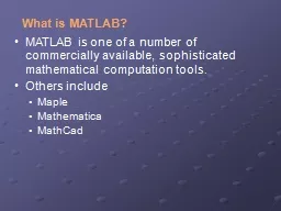
Programming With MATLABSimulink September 10 2016 1 BISON BEST What Youll Need Minimum System Requirements Microsoft Windows 7 or Later 32bit or 64bit machine Administrator Access on the PC ID: 673349

2016 september 2016bison 127 september 2016 127 2016bison key robotics 2010 reserved rights click digital copyright simulink bison motors

Share:

Link:

Embed:

Download Presentation from below link

Download Presentation The PPT/PDF document "BEST Robotic, Inc. MATLAB/Simulink Team ..." is the property of its rightful owner. Permission is granted to download and print the materials on this web site for personal, non-commercial use only, and to display it on your personal computer provided you do not modify the materials and that you retain all copyright notices contained in the materials. By downloading content from our website, you accept the terms of this agreement.


Presentation Transcript

Slide1

BEST Robotic, Inc.MATLAB/Simulink Team Training

Programming With MATLAB/Simulink

September 10, 2016

1

BISON BESTSlide2

What You’ll Need…

Minimum System RequirementsMicrosoft Windows 7 or Later32-bit or 64-bit machineAdministrator Access on the PC Internet connection

Software requiredMATLAB R2016a free version available at http://www.mathworks.comGo to mathworks.comSearch “Best Robotics”On the search List, choose “BEST Robotics”Click “Request Software”If you are not registered at Mathworks, you will be asked to create an accountYou will get an approval by email in minutes.Installation instructions will be provided in the approval emailAssociate to your license to your registered accountDownload and install MATLAB from the link provided (about 40 minutes)Activate the MATLAB

September 10th, 2016

2

Bison BESTSlide3

Key Software Locations

September 10

th, 2016

3

Bison BESTSlide4

Click on the MATLAB r2015b link

Starting MATLAB

September 10, 2016

4

Bison BESTSlide5

September 10, 2016Bison BEST

5

What You’ll Need…

After installing MATLAB, choose Apps-> Get More AppsSlide6

September 10, 2016Copyright © 2010 BEST Robotics, Inc. All rights reserved.

6Slide7

September 10, 2016Bison BEST

7

Choose Apps, then VEX CompanionAfter the VEX block opens, choose Get Support Package(Must be connected to the internet)Slide8

September 10, 2016BISON BEST

8

MathWorks Website opens, Click Get Support Package and follow instructions for installation.At the end of installation, it helps to restart MATLABSlide9

Something on MATLAB

September 10, 2016

9

Bison BEST

MATLAB Window Opens: MATLAB means Matrix Laboratory. It is textural programming environment.It can execute commands directly as typed in the command window or run a script code from a saved fileFamiliarize yourself with the three tabs: HOME, PLOTS, APPSSlide10

MATLAB Simulink

Simulink is MATLAB’s graphical programming interface.Programming is accomplished by connecting various graphical icons in a specific order.Simulink graphical icons are collected in what are known as Libraries.Simulink programs are known as

ModelsThe Simulink Library collection is opened by clicking the Simulink library icon

September 19, 2015

10

Copyright © 2010 BEST Robotics, Inc. All rights reserved.Slide11

Choose Apps from the main menu

For BEST Robotics tools

September 10, 2016

11

Bison BESTSlide12

….Best Robotics tools

September 10th, 2016Bison BEST

12Choose VEX CompanionSlide13

Using VEX SupportSeptember 10, 2016

Bison BEST13Mathworks

VEX support is embedded in Simulink, which is accessed using the following interface Slide14

September 10, 2016

Copyright © 2010 BEST Robotics, Inc. All rights reserved.

14

Simulink VEX Library

To open Simulink VEX Library, Click Open Library

NOTE: The Library window may be

hidden far to the right of your screenSlide15

Before Creating your Program

You must know what you want to achieveThe connection layout of motors and servos to the Cortex controller.The assignment of Joystick keys and their intended control functions.How the joysticks will control the motors and servosAny other interaction between the Cortex controller and the hardware such as sensorsSeptember 19, 2015

Bison BEST15Slide16

The Typical BEST Robot Model

The robot can be driven either in Tank or in Arcade mode.The joystick has four analog channels and four digital channels

The controller can drive Up to 10 motors and servos in analog modeUp to 4 servos in digital modeCan read up to 8 analog sensors (such as potentiometers)Can read up to 8 digital sensors (such as limit switches)Simulink library has an icon for each of the possible functions: to read the joystick, to drive motors and servos, and to read sensors.Our next example robot will run in arcade driven by two motors; there will be two actuator motors, one with a limit switch and four servosAnalog joysticks to motors and digital sticks to servos

September 10, 2016

16

Copyright © 2010 BEST Robotics, Inc. All rights reserved.Slide17

Creating a Simulink Robot Program

Open a robot model window by clicking the “Create new model” button on the VEX Support Package Companion menu

September 10, 2016

Bison BEST

17Slide18

The BEST Robot Model

September 10, 2016

18

Copyright © 2010 BEST Robotics, Inc. All rights reserved.Slide19

+ 127

+ 127

- 127

- 127

+ 127

+ 127

- 127

- 127

The joystick and accelerometer limit return values are +127 and -127 as shown in the figure. The buttons have a return value of 0 when pressed and 1 when released.

Accelerometer rotate right limit + 127

Accelerometer rotate left limit - 127

Accelerometer rotate forward limit + 127

Accelerometer rotate back limit - 127

Reading the

Joystick Signals

Y Axis

X Axis

September 10, 2016

19

Copyright © 2010 BEST Robotics, Inc. All rights reserved.

12

Digital

signals (button) on 4 channels

4 Analog signals on four channels (two joysticks)

2 Accelerometer signals (roll and pitch)Slide20

September 10, 2016

20

Copyright © 2010 BEST Robotics, Inc. All rights reserved.Slide21

Start building your robot controllerClick and drag one Game pad button and one Game pad joystick from the VEX Library into your untitled model.

September 10, 2016Bison BEST21Slide22

…robot controller buildingMake four copies of gamepad joystick and four copies of gamepad buttons

September 10, 2016Bison BEST22Slide23

Actuating Motors and Servos

September 10, 2016

23

Copyright © 2010 BEST Robotics, Inc. All rights reserved.Slide24

Actuator Controls

September 19, 2015

24

Copyright © 2010 BEST Robotics, Inc. All rights reserved.Slide25

September 19, 2015

25

Copyright © 2010 BEST Robotics, Inc. All rights reserved.

Add motors and ServosSlide26

Convenience Libraries

September 10, 2016

26

Copyright © 2010 BEST Robotics, Inc. All rights reserved.Slide27

Contents of the Utilities module

September 10, 2016Bison BEST

27Slide28

MotorsDrag the Arcade module into your model. Connect two motors and two analog joysticks as

Drag the two digital inputs (to serve as limit switches) and one Limit switch control block in the model. Connect the motor, limit switch and joystick September 10, 2016Bison BEST

28Slide29

… Finish the connection

September 10, 2016

29

Copyright © 2010 BEST Robotics, Inc. All rights reserved.Slide30

Set

the joystick channels

September 10, 2016

30

Copyright © 2010 BEST Robotics, Inc. All rights reserved.

Double click on each joystick and set its channel:

Valid channels are from 1 to 4Slide31

Set

the digital button channels

September 10, 2016

31

Copyright © 2010 BEST Robotics, Inc. All rights reserved.

Double click on each digital button and set its channel and the button: Valid channels are from 5 to 8, valid buttons are UP and DOWNSlide32

Set channel for Digital Input Limit SwitchesSeptember 10, 2016

Bison BEST32

Double click on each digital limit switch and set its channel: Valid channels are from 1 to 12Slide33

Set motor and servo channelsSeptember 10, 2016

Bison BEST33

Double click on each motor and each servo and setting their channels: Valid channels are from 1 to 10Leave gear ratio at 1/13.5Slide34

Working with Digital ButtonsMotors and servos require inputs of from -127 to +127 to run in either direction at full speed, full range.

Analog joysticks spits numbers from -127 to +127, so can drive motors and servos as required.At this time joysticks are ready to run Digital buttons spits only two numbers, 0 and 1, therefore it cannot drive motors and servos.If the output is multiplied by 127, then it can drive the motor full speed on one direction or open servo full range one direction.The direction can be reversed by multiplying by output by -127.No way to drive the motor or servo in both directions

September 10, 2016Bison BEST34Slide35

Multiplication by 127The Math Library has a Gain icon

You can place the gain between the digital button and the servoDouble click on it and set the gain to 127September 10, 2016Bison BEST

35Slide36

Minimize the Vex Library, click MATLAB’s Home Tab and Open the Simulink Library

September 10, 2016Bison BEST36Slide37

Conditioning the digital command

Open Ports & Subsystems Library, and click and drag “Subsystems” into your model.September 10, 2016Bison BEST

37Slide38

Conditioning the digital signalSeptember 10, 2016

Bison BEST38

Double click on that subsystem boxClick on the line that joins In1 and Out1, and delete itSlide39

Conditioning the digital signalMake a copy of

In1 so you have two inputs September 10, 2016Bison BEST39

In Simulink Library again choose the Stateflow Library, click and drag the Chart into your subsystemSlide40

Conditioning the digital signal

Double click on the Chart to pen the chart editorSeptember 10, 2016Bison BEST

40Slide41

Click and drag three states; label the first as UP_KEY, the second as NO_KEY and the third as DOWN_KEY

Put the mouse pointer at the left edge of the NO-KEY icon, press the left Key (of the mouse), and move the mouse pointer( while the key is still pressed) towards the UP-KEY icon. This draws an arrow from the NO_KEY state to the UP_KEY state.

September 10, 2016Bison BEST41Slide42

Put the mouse pointer at the left edge of the NO-KEY icon, press the left Key (of the mouse), and move the mouse pointer( while the key is still pressed) towards the UP-KEY icon. This draws an arrow from the NO_KEY state to the UP_KEY state.

Point and click at the leftmost part of the arrow to move the question mark there. Fill the question mark with the following command:[UP==1&&OUT<127]{OUT=OUT+127;} September 10, 2016

Bison BEST42Slide43

Repeat the process using the following equations

From UP_KEY to NO_KEY [UP==0]From NO_KEY to DOWN_KEY[DOWN==1&&OUT>-127]{

OUT=OUT-127;} From DOWN_KEY to NO_KEY[DOWN==0]September 10, 201643Slide44

September 20

th, 2014Bison BEST44

Now add the default setting with {OUT=0;}Slide45

Choose Tools ->

Model ExplorerSeptember 10, 2016Bison BEST45

Choose chartFilter:States/Functions…Transitions…Data …Slide46

Add Data

September 10, 2016Bison BEST46Slide47

Assign created data to functionsChange View to Stateflow

, For the first data change scope to Output and Name to OUT (case sensitive). Click ApplySeptember 10, 2016Bison BEST

47Slide48

For the second and third elements, change Scope to Input; Name them UP and DOWN

September 10, 2016Bison BEST48Slide49

Drag the Gain icon and make as many copies as the digital joysticks that you have

September 10, 2016Bison BEST49Slide50

Close the Model explorer, (File->Close)

Rename the nodes as follows (case sensitive): In1 becomes UP In2 becomes DOWN Out1 becomes OUTSeptember 20

th, 2014Bison BEST50Slide51

Complete the connections

Click the Back ArrowSeptember 10, 2016Bison BEST

51Slide52

Finish

Two buttons will now control one servor in both directions, so we remove one servo or we add another buttonSeptember 10, 2016Bison BEST

52Slide53

After Building the Model

September 10, 2016

53

Copyright © 2010 BEST Robotics, Inc. All rights reserved.

Save the simulink model file You may want to Simulate the model before downloading into your Vex Controller.

Open the utilities block again (if it is closed)

Pay attention to the

Simulation Input

, and the

Simulation Output

collectionsSlide54

September 10, 2016

54

Copyright © 2010 BEST Robotics, Inc. All rights reserved.Slide55

Simulating the Arcade

September 10, 2016

55

Copyright © 2010 BEST Robotics, Inc. All rights reserved.

Pull a variable input, a the field simulator and a toggle. Make as mane copies as necessaryConnect the variable inputs to the inputs of the joysticks

Connect the

toggles

to the inputs of the joysticks

Connect the field simulator to the two drive motorsSlide56

Simulation Control

August 1, 2010

56

Copyright © 2010 BEST Robotics, Inc. All rights reserved.Slide57

After Simulation

Remove all simulation signals and Simulation inputs on all joysticks and digital buttons and inputs. Double click and uncheck “Add Input Port for Simulation”

Do the same to remove simulation outputs from motors and servosSave your model file

September 10, 2016

57

Copyright © 2010 BEST Robotics, Inc. All rights reserved.Slide58

Upload program into VEX controller and runSeptember 10

th, 2016Bison BEST58Deploy to HardwareSlide59

Additional support

http://www.mathworks.com/academia/student-competitions/best-robotics/

September 10th, 2016

Bison BEST

59