/
IOSR Journal of IOSR Journal of

IOSR Journal of - PDF document

lois-ondreau
lois-ondreau . @lois-ondreau
Follow
369 views
Uploaded On 2016-05-20

IOSR Journal of - PPT Presentation

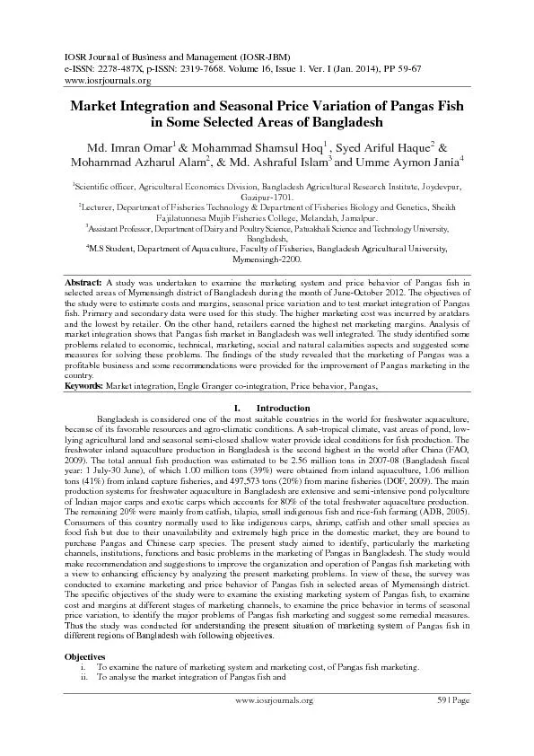
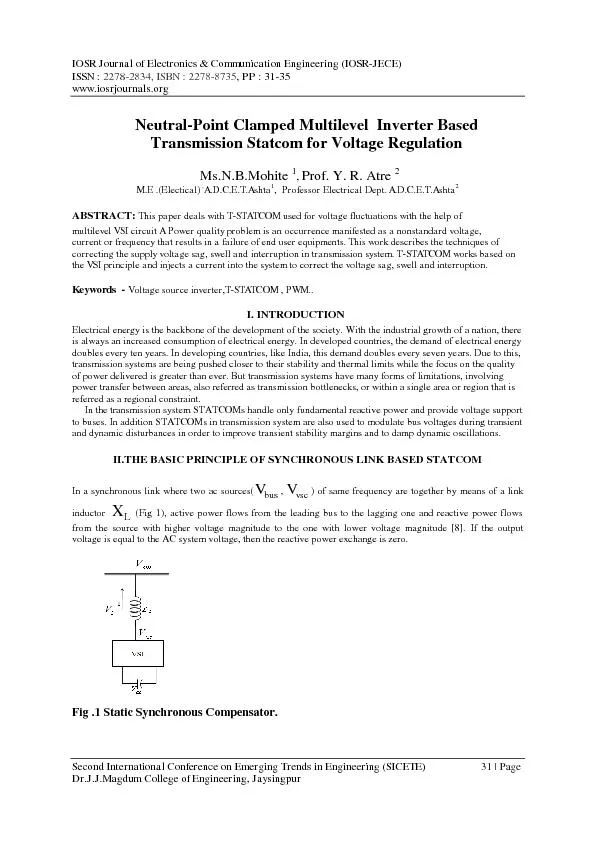
Electronics Communication Engineering IOSR JEC E ISSN 2278 2834 ISBN 2278 87 35 PP 31 35 wwwiosrjournalsorg Second International Conference on Emer ging Trends in Engineerin ID: 327954

Electronics Communication Engineering (IOSR - JEC E) ISSN

Share:

Link:

Embed:

Download Presentation from below link

Download Pdf The PPT/PDF document "IOSR Journal of" is the property of its rightful owner. Permission is granted to download and print the materials on this web site for personal, non-commercial use only, and to display it on your personal computer provided you do not modify the materials and that you retain all copyright notices contained in the materials. By downloading content from our website, you accept the terms of this agreement.


Presentation Transcript

IOSR Journal of Electronics & Communication Engineering (IOSR - JEC E) ISSN : 2278 - 2834 , ISBN : 2278 - 87 35 , PP : 31 - 35 www.iosrjournals.org Second International Conference on Emer ging Trends in Engineering (SICETE) 31 | Page Dr.J.J.Magdum College of Engineering, Jaysingpur Neutral - Point Clamped Multilevel Inverter Based Transmission Statcom for Voltage Regulation Ms.N.B.Mohite 1 , Prof. Y. R. Atre 2 M.E .(Electical) , A.D.C.E.T.Ashta 1 , Professor Electrical Dept. A.D.C.E.T.Ashta 2 ABSTRACT : This paper deals with T - STATCOM used for voltage fluctuations with the help of multilevel VSI circuit A Power quality problem is an occurrence manifested as a nonstandard voltage, current or frequency that results in a failure of end user equipments. This work describes the techniques of correcting the supply voltage sag, swell and interruption in transmission system. T - STATCOM works b ased on the VSI principle and injects a current into the system to correct the voltage sag, swell and interruption. Keywords - Voltage source inverter,T - STATCOM , PWM.. I. INTRODUCTION Electrical energy is the backbone of the development of the society. With the industrial growth of a nation, there is always an increased consumption of electrical energy. In developed countries, the demand of electrical energy doubles every ten years. In developing countries, like India, this demand doubles every seven ye ars. Due to this, transmission systems are being pushed closer to their stability and thermal limits while the focus on the quality of power delivered is greater than ever. But transmission systems have many forms of limitations, involving power transfer b etween areas, also referred as transmission bottlenecks, or within a single area or region that is referred as a regional constraint. In the transmission system STATCOMs handle only fundamental reactive power and provide voltage support to buses. In addition STATCOMs in transmission system are also used to modulate bus voltages during transient and dynamic disturbances in order to improv e transient stability margins and to damp dynamic oscillations. II.THE BASIC PRINCIPLE OF SYNCHRONOUS LINK BASED STATCOM In a synchronous link where two ac sources( , ) of same frequency are together by means of a link inductor ( F ig 1 ), active power flows from the leading bus to the lagging one and reactive power flows from the source with higher voltage magnitude to the one with lower voltage magnitude [8]. If the output voltage is equal to the AC system voltage, then the reactive power exchange is zero. F ig .1 Static Synchronous Compensator. Neutral - Point Clamped Multilevel Inverter Based Trasmission Statcom for Voltage Regulation Second International Conference on Emerging Trends in Engineering (SICETE) 32 | Page Dr.J.J.Magdum College of Engineering, Jaysingpur III.THE THREE - LEVEL NPC VSI Fig.2 Diode ClampedThree - Level Inverter. The diode - clamped inverter [5] was also called the neutral - point clamped (NPC) inverter because when it was first used in a three - level inverter the mid - voltage level was defined as the neutral point level. A three - level diode - clamped inverter is show n in Fig. 2. In this circuit, the dc - bus voltage is split into three levels by two series - connected bulk capacitors, C 1 and C 2 . The middle point of the two capacitors N can be defined as the neutral point. The output voltage V AN has three states: V dc /2, 0, and - V dc /2. For voltage level V dc /2, switches S 1 and S 2 need to be turned on; for - V dc /2, switches and need to be turned on; and for the 0 level, and need to be turned on. Table 3.1 shows the switch status and definition of state for phase A of diode clamped inverter. The two diodes D 5 and D 6 clamp the switch voltage to half the level of the dc - bus voltage. When both and turn on, the voltage across A and O is V dc , i.e., V AO = V dc . In this case, D 6 balances out the voltage sharing between and with blocking the voltage across C 1 and blocking the voltage across C 2 . Some of the important features of diode clamped inverter are given below: Low voltage power semiconductor devices: The m - level diode clamped inverter requires (m+1) active devices (GTO and IG BT’s etc) per phase and each active device will see a blocking voltage of (V dc / (m - 1)). Duty cycle of switching devices: The duty cycle of the power switches is different. So switches of different current rating have to be used for optimal design. (a) Rating for clamping diodes: For five and higher level inverters, the voltage blocking capability of the diodes are different. So the diodes will have different voltage ratings. Assuming that the characteristics of diode s are identical, then multiple diodes of same voltage rating have to be used to achieve required voltage - blocking capacity. Hence, for a sufficiently large number of levels, the number of diodes required will become too large and will make the circuit less reliable. Also power circuit layout and packaging becomes difficult. (b) Capacitor voltage unbalance: The mid point voltage is derived using capacitors and these carry load current. Unequal loading of the capacitors leads to imbalance in the dc bus capacitor voltages and this will cause the Neutral - Point Clamped Multilevel Inverter Based Trasmission Statcom for Voltage Regulation Second International Conference on Emerging Trends in Engineering (SICETE) 33 | Page Dr.J.J.Magdum College of Engineering, Jaysingpur dc mid pint voltage to drift. This is not a serious problem for utility applications such as, static VAR generators (SVG), active power filters, etc., where the inverters need to supply only the reactive power. (c) High voltage surge: During turn off, the devices will experience a high transient over voltage and also snubbers are required to distribute the voltage across clamping diodes in a uniform fashion. The design of snubbers is complicated, as the current through these snu bbers is bi - directional. When the number of output levels is sufficiently high, the inverter system required a huge number of clamping devices due to the series connection of clamping diodes and capacitors. These not only increase the cost of the system, but also controlling the inverter output and capacitor voltage balance becomes more complex when the number of levels is higher than five. Thus diode clamped inverters are usually limited to three or (maximum) . IV.CONTROL STRATEGY . Fig.3 Main circuit and control block diagram of T - STATCOM. The main objective of this control method is to control the phase angle of the inverter output [9] with respect to the changes in the system reactive power. The quantities obtained from above algorithm s are used to calculate the system reactive power and phase angle (ωt). The measured reactive power is then compared with reference value to produce error signal, which is then passed through a PI controller to obtain the required phase angle α. Pulses re quired for the inverter are generated from SWPM block. By controlling the phase angle α of inverter output voltage, the DC capacitor voltage can be changed. Thus, the amplitude of the inverter output voltage can be controlled. Schematic representation of t he control circuit as shown in fig (3). V.SPWM Technique Fig 4. Phase A of three - level inverter. Neutral - Point Clamped Multilevel Inverter Based Trasmission Statcom for Voltage Regulation Second International Conference on Emerging Trends in Engineering (SICETE) 34 | Page Dr.J.J.Magdum College of Engineering, Jaysingpur Table 1: Switching pattern . Fig.5 Triangular - Sinusoidal PWM Control for Three - Level NPC Inverter Here a single reference sine wave (Va) is compared with two carriers waves (T H, higher carrier wave and T L, lower carrier wave) to generate pulses. The pulses generated by comparing Va with T H and Va with T L. The switch is on when �Va T H , is on when �Va T L , is on when is off and is on when off. When the compensator current is controlled indirectly varying the converter output voltage, it is called indirect current controlled [11]. By controlling the phase angle of the inverter output voltage, the dc capacitor voltage V dc can be changed. Thus, the amplitu de inverter output can be controlled. Phase angle control method is an example for indirect control. VI. PHASE ANGLE CONTROL METHOD The three phase AC signals are transformed into the stationary two phase quantities using Clarke’s transformation and then the stationary quantities are transformed to the rotating synchronous reference frame (SRF). If the system voltages are balanced the SRF quantities will be dc quantities and if there is any unbalance in the system the transformed quantities will not b e DC. Consider the following three phasors. = 1 ∠ 0 0 (4.1) = 1 ∠ − 120 0 (4.2) Switches on Switches off Output voltage , , +V DC , , 0 , , - V DC Neutral - Point Clamped Multilevel Inverter Based Trasmission Statcom for Voltage Regulation Second International Conference on Emerging Trends in Engineering (SICETE) 35 | Page Dr.J.J.Magdum College of Engineering, Jaysingpur = 1 ∠ 120 0 (4.3) These three phasors are converted to the two phase form using Clarke’s transform ation the Clarke's transformation matrix is given below 0 = 2 3 ۏ ێ ێ ێ ۍ 1 − 1 / 2 − 1 / 2 0 √ 3 2 − √ 3 2 1 √ 2 1 √ 2 1 √ 2 ے ۑ ۑ ۑ ې (4.4) Now these two phase stationary quantities are converted to rotating form using the Park's transformation as 0 = cos sin 0 − sin cos 0 0 0 0 0 (4.5) The phase angle used in the above transformation is obtained from phase locked loop (PLL) which is described in next section . VII.CONCLUSION A new Voltage source inverter based T STATCOM using three - level inverter is proposed for high voltage and high power applications. Using the model, a new control method which control sthe phase angle gives fast response . Voltage source inverter is used to compensate the voltage fluctuations at the receiving end voltage. STATCOM can provide both capac itive and inductive compensation and is able to control its output current over the rated maximum capacitive or inductive range independently of the ac system voltage. voltage dips mainly have their origin in the higher voltagr levels, are removed by using this technique. If the economical losses due to voltage dips are significant, mitigation actions can be profitable for the customer REFERENCES 1. N.G Hingroni and I Gyugyi. “Understanding FACTS: Concepts and Technology of flexible AC Transmission System ”, I EEE Press, New York, 2000. 2. E.Acha, V.G.Agelidis, O Anaya - Lara and T.J.E.Miller, “ Power Electronic Control in Electrical Systems ”, Newnens Power Engineering Series 2002 3. K R Padiyar “ FACTS controllers in power transmission and Distribution ”, New Age Interna tional Publishers, First Edition 2007. 4. Muhammad H. Rashid “ Power Electronics circuits, devices and applications ”Pearson Education, third edition, 2004. 5. G.Sundar ,S.RamaReddy,“Digital Simulation of D - Statcom for voltage fluctuations”, International Journal of Engineering Science and Technology Vol. 2(5), 2010, 1131 - 1135 6. J. S. Lai, F. Z. Peng “ Multilevel converters - a new breed of power converte r”, IEEE Trans. on Ind. Appl., Vol. 32 No 3 pp. 509 - 517, 7. Jose Rodriguez, Jih - sheng Lai “Multilevel Inverters : A S urvey of Topologies, Control, and Apllications ”, IEEE Trans. on Ind. Elec., Vol. 49 No 4 pp. 724 - 738, 2002. 8. Nabae A, Takahashi I., Akagi H “A New Neutral Point Clamped PWM Inverter ”, IEEE Trans. On IA., 1981, IA - 17(5), pp. 509 - 517. 9. Kalyan K Sen “STATCOM - S TATic synchronous COMpensator: Theory, Modeling, and Applications” 1998 ,IEEE. 10. Mustapha Benghanem , Azeddine Draou “ A New Modeling and Control Analysis of an Advanced Static Var Compensator using A Three - level (NPC) Inverter Topology” Journal of Elec trical Engineering, Vol. 57, No.5, 2006, pp 285 - 290. 11. J.B.Ekanayake , N.Jenkins “Mathematical models of a three - level advanced static VAr compensator”IEEE,Vol.144, pp201 - 206