/
Laser / RF Timing ( E ngineering of Femtosecond Timing Systems) Laser / RF Timing ( E ngineering of Femtosecond Timing Systems)

Laser / RF Timing ( E ngineering of Femtosecond Timing Systems) - PowerPoint Presentation

lois-ondreau
lois-ondreau . @lois-ondreau
Follow
343 views
Uploaded On 2019-11-03

Laser / RF Timing ( E ngineering of Femtosecond Timing Systems) - PPT Presentation

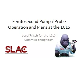
Laser RF Timing E ngineering of Femtosecond Timing Systems Josef Frisch SLAC Femtoseconds Bryan Bandli Scanning Electron Microscopy Laboratory University of Minnesota 70fs Eye blink ½ human hair ID: 762865

noise laser timing phase laser noise phase timing signal optical time diode jitter systems power system amplitude frequency detection

Share:

Link:

Embed:

Download Presentation from below link

Download Presentation The PPT/PDF document "Laser / RF Timing ( E ngineering of Femt..." is the property of its rightful owner. Permission is granted to download and print the materials on this web site for personal, non-commercial use only, and to display it on your personal computer provided you do not modify the materials and that you retain all copyright notices contained in the materials. By downloading content from our website, you accept the terms of this agreement.


Presentation Transcript

Laser / RF Timing(Engineering of Femtosecond Timing Systems) Josef FrischSLAC

Femtoseconds Bryan Bandli , Scanning Electron Microscopy Laboratory, University of Minnesota 70fs Eye blink ½ human hair at C 1 Meter of typical engineering material will change length by 30fs/°C 2 5000 Years 0.1 second 70 femtoseconds

Measuring Femtoseconds - Narrow Band Clocks Conventional electronic triggers only good to ~1ps. Use repetitive clock to average timing measurements on millisecond timescales to allow X1000 improvement using GHz clocks 3

Why use RF? Thermal noise (at room temperature) is -174dBm in a 1Hz bandwidthI n a 1 KHz bandwidth, thermal noise is -144dBm or 4 AttowattsA 1 mW , 1KHz bandwidth, 10dB noise figure system would have a signal to noise of 134dBm, corresponding to an amplitude signal to noise of 2x10 -7 . For a 1GHz system this is a timing noise of 30 attoseconds Noise is rarely the only limit for measuring timing Generally there is a trade-off between noise and linearity. RF hardware is robust and relatively inexpensive. 4

RF LinearityAmplitude to phase conversion is a major source of timing drift and noiseTypical phase detection frequencies are ~2GHz ( ω=10GHz), so 100fs represents only 10-3 Radian Very difficult to measure AM-> PM due to the lack of a method to produce amplitude variation without associated phase variation.AM->PM is a form of nonlinearity, so it is possible to make an estimate by measuring other nonlinear terms (amplitude nonlinearity). Linearity typically specified at IP3. (Third Order Intercept point): hypothetical power were the 3rd order nonlinear terms equal the linear terms. Nonlinear terms scale (in dB) as 3X input power, so nonlinear contribution goes as 2X input. 20dB below the IP3 point is -40db nonlinearity, or 1% amplitude 5

Accelerator Timing – RF Gun Photo-emission typically off crest Energy spread produces compression For LCLS gun, beam time is equally controlled by laser and RF timing RF time set by phase measurement using gun pick-off Feedback can be pulse to pulse or continuous Beam time is not completely determined by laser time For a gun with no compression, locking isn’t needed! 6

7 Choice depends on relative phase noise and modulation bandwidth of the laser and RF source. For Ti:Sapphire lasers the phase noise is typically higher than for RF sources and usually the laser is locked to the RF master oscillator.

Laser Locking SystemsMost rely on locking the ~100MHz mode-locked laser oscillator to a reference signal Commercial laser -> RF locking systems available at the ~100s of fs noise levelCan to better with custom systems Ti:Sapphire lasers are the most commonly used, but fiber lasers have lower timing noise and are gaining popularity.Significant variation in the unlocked noise of different laser oscillators – directly impacts locked performance8

Laser Systems Mode locked laser frequency -> phase determined by optical cavity length Optical cavity length usually controlled with piezo-electric mirrorPulses are stretched before amplification to avoid peak power damage Stretching / amplification / compression can add significant jitter. 9

Phase DetectionGenerally the most challenging part of the laser locking systemLaser diodes produce short (~100ps) pulses at fairly low rate (~100MHz) Use bandpass filters to ring the signal into a near continuous RF tone Filtering is worse for signal to noise, but better for linearity!Resulting power can be very low (<microwatt), but still enough above thermal noise to do 10s of femtosecond phase detection. Use a mixer to compare the phase with the reference system10

Photodiode Phase Detection Signals Reference Laser diode out Filtered laser diode Mixer output LP filter output Matlab calculation with 68MHz laser frequency and 476MHz locking frequency 11

Photodiode Error SourcesAmplitude -> phase conversion 10GHz diodes typically biased at 5VIf peak output voltage becomes comparable to the bias, the capacitance of the diode can change and cause a phase shift Remember that we are looking at timing shifts on the order of <1/1000 of the diode pulse width.Position sensitivityTypical 10GHz photodiode (ET-4000) has a 40micron diameter – corresponds to about 500fs for signals to cross the diode!Improved diodes: High linearity fiber coupled diodes available.Looks like an overall improvementNeeds care to have long term stable coupling to single mode optical fiberAvailable from Discovery Semiconductor. (IP3 > 40dBm!) 12

Mixer LO Leakage Errors A small amount (~-30dB coupling) of the high power LO reference will leak into the low power RF input This causes a shift in phase of the input RF signal from the diode that depends on the amplitude of the RF signalsSince LO is usually stable, can make feedback setpoint to be the offset from the LO. Can improve by using high gain amplifiers on the diode signal, BUT IP3 limits in the mixer andhigh gain systems can have cross talk from other signals 13

Heterodyne System Mix to an intermediate frequency rather than DC (frequencies from SLAC system) Low frequency phase detection much easier:Can easily digitize and calculate relative phase in softwareCan use low frequency mixer or analog multiplier with much better performance than RF mixer Signal levels small until RF mixer, then put gain at low frequency where cross talk is less significant. Technique used in radio receivers (R. Fessenden , 1901 (!!!)) 14

Multiplying the Laser Rate M. Csatari Divall1 et al. 15 Potential to significantly improve noise / linearity of diode detection systems Adds some optical system complexity

Electro-optical phase detectionElectro-optical modulator “multiplies” RF signal X optical signal – acts like a mixer Commercial devices available to very high bandwidth (~50GHz)Optical signal detection is low frequency, can use large diodes that can tolerate high signal levels -> good signal / noise / nonlinearity Techniques to correct for amplitude drift and fiber length changes16 Concept: differential measurement immune to RF amplitude and opitcal power drifts Sagnac interferometer uses single phase modulator and fiber loop to cancel fiber length drifts, and detector offset drifts.

Diode detector vs electro-optical phase detection Similar detection frequencies – 10s of GHzPhotodiodeSignal limited by diode non-linearity Bandpass filter reduces signalRF noise limits to ~1fs in 10Khz bandwidthSensitive to laser amplitude fluctuationsElectro-opticalSignal limited by max power in fiber (~100pJ)Shot noise limits theoretical resolution to ~0.1fS in 10KHz bandwidthSensitive to laser wavelength changes In practice other system effects are usually the limit well before you reach 1fs. 17

Laser Phase ControlLaser cavity length controlled by piezo-electric driven mirror in most commercial femtosecond lasers.Typical resonance of 10s of KHz sets upper bandwidth limit for feedback – feedback usually rolled-off at few-10 KHz Need high current, low noise drive amplifierBeware of noise sources – found that in Coherent Vitara lasers the largest noise source was the driver for the low bandwidth piezo “starter” mirrorFixed with diode circuit to block noise: 18 Don’t miss the simple stuff!!!

Laser Amplifier and TransportIn installed systems the laser amplifier / transport chain appears to add substantial jitter: SLAC / MEC: oscillator / FEL jitter < 100fs, but measured optical to X-ray jitter >150fsPSI: Oscillator jitter < 30fs, amplified pulse jitter >150fs ( Divall Marta et al)100s of fs increased jitter seen at Max Plank T Mirua , et al December 15, 2000 / Vol. 25, No. 24 / OPTICS LETTERS 1795 Short term jitter relative to mode-locked laser ~10fs Long term drift 100fs/hour 19

Compressor / ExpanderExperimental and theoretical investigation of timing jitter inside a stretcher-compressor setup. Sandro Klingebiel, et al, 13 February 2012 / Vol. 20, No. 4 / OPTICS EXPRESS 3443 Steering due to air currents in compressor can cause ~100fs/ microradian timing shifts. 20

Timing CorrectionsAmplifier / transport chain:Can use an optical cross- correlator to compare the mode-locked laser time with the output of the amplified systemE-beam arrival time monitors Resonant cavities – demonstrated at SLAC to 7fs RMS (at 150PC), 20fs RMS at 20pCElectro-optical arrival time monitors – Demonstrated at DESY to 3fs RMS at 300pc. Transverse cavity deflectors – timing resolution limited by RF system noise ~30fs, work at low charges.Can be used for offline correction of experiment data21

“Physics” Timing For RF guns, the charge depends on the relative phase of the RF fields and the laser If QE is stable, you could feedback laser time on photocathode current!Can move to zero-current phase (Schottky edge) to find “zero” time in a few seconds (done at LCLS) The experimental chamber will need to provide a way to find zero-time. Separate “experiment” setup or possibly from the main experiment. The time between finding T0 will determine the long term drift requirements

CommentsBelow 100fs things become more difficult, 10fs is fairly heroic. Laser locking systems can be complex and expensive – especially on the scale of electron diffraction experimentsDon’t build a more complex system that you need Most straightforward approach is to lock the laser oscillator to the accelerator RF reference using photodiodesCan use beam arrival time monitors and cross-correlators to correct experiment data offline.Added costs and complexityWhere possible use physics measurements to directly measure timing. 23 Many sub-systems, concentrate on the ones that limit performance, not the most interesting ones: Timing is a tool, not an experiment