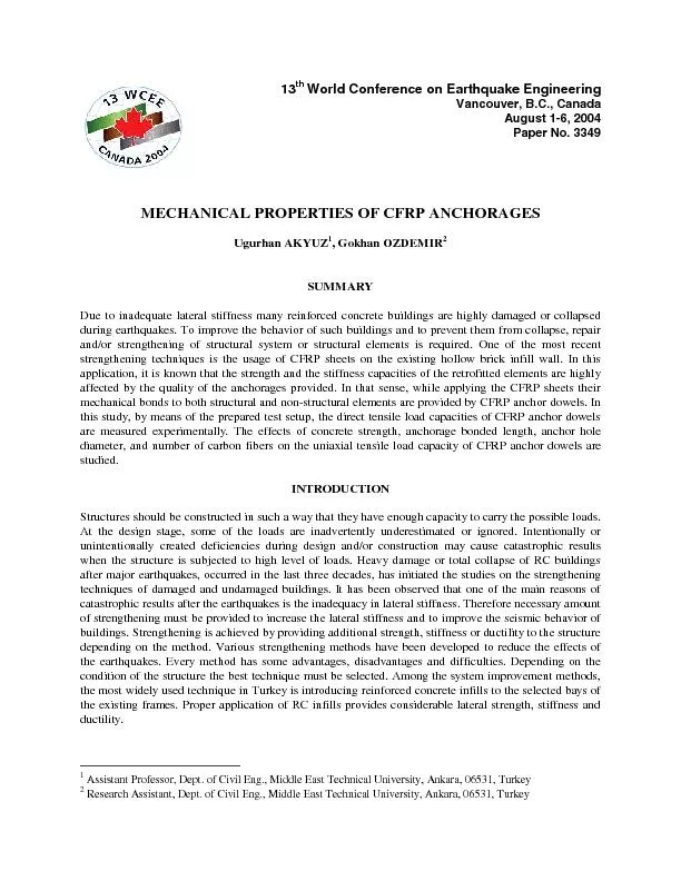
/
CONCLUSIONS In this experimental study, effects of CFRP sheet width, b CONCLUSIONS In this experimental study, effects of CFRP sheet width, b

CONCLUSIONS In this experimental study, effects of CFRP sheet width, b - PDF document

luanne-stotts
luanne-stotts . @luanne-stotts
Follow
399 views
Uploaded On 2016-05-10

CONCLUSIONS In this experimental study, effects of CFRP sheet width, b - PPT Presentation

In Figure 10 the effect of CFRP sheet width with changing compressive strength of concrete is given This figure indicates that concrete strength on the load carrying capacity of anchor dowel does n ID: 313251

Figure the effect

Share:

Link:

Embed:

Download Presentation from below link

Download Pdf The PPT/PDF document "CONCLUSIONS In this experimental study, ..." is the property of its rightful owner. Permission is granted to download and print the materials on this web site for personal, non-commercial use only, and to display it on your personal computer provided you do not modify the materials and that you retain all copyright notices contained in the materials. By downloading content from our website, you accept the terms of this agreement.


Presentation Transcript

CONCLUSIONS In this experimental study, effects of CFRP sheet width, bonded length, hole diameter and compressive strength of concrete on the uniaxial tensile capacity of the CFRP anchor dowels were investigated. The results obtained from this study provide experimental information for the design of bond-type CFRP anchor dowel. These experimental results should be verified with analytical studies. In literature, an analytical study on uniaxial tensile capacity of the CFRP anchor dowel is not given. The next stage of this study will be the analytical investigations. Before giving the conclusions, the authors are willing to strongly emphasize that the labor quality in these experiments are very important and it can significantly influence the obtained results. In order to have a perfect bond between the structural element and the dowel, there should be at least 1 or 2 mm free space for the epoxy resin. The tests in narrow holes, at which the hole diameter was almost equal to diameter of the CFRP anchor dowel, resulted with a slip of the CFRP anchor at a very low tensile force. This was due to insufficient amount of epoxy resin which provides a poor bond between these two members. As it is expected, maximum load capacity increases with an increase in CFRP sheet width. This indicates that the capacity of a CFRP anchor is directly related to the number of carbon fibers in the sheet. In the range of parameters taken in this study, the test results showed that the capacity did not increase, even decrease in some cases, after a bonded length of 100 mm. Similar to study of Zhang et al [8], which gave an effective bond length for CFRP rods, for CFRP anchor dowels there is also an effective bonded length being equal to 100 mm. ACKNOWLEGMENT This study was conducted at the Structural Mechanics Laboratory of Middle East Technical University, and is partially supported by the Scientific and Technical Research Council of Turkey. REFERENCES 1. Ersoy U. and Uzsoy S. “The Behavior and Strength of Infilled Frames.” Report No. MAG-205, TUBITAK, 1971; Ankara, Turkey. 2. Higashi Y. and Kokusho S. “The Strengthening Method of Existing Reinforced Concrete Buildings”, U.S.-Japan Cooperative Research Program in Earthquake Engineering, 1975; Honolulu H1. 3. Endo T., Adachi, H., Nakanishi, M. (1980). “Force-Deformation Hysteresis Curves of Reinforced Concrete Shear Walls.” Proc. of the 7th WCEE, V. 6, Istanbul, Turkey. 4. Triantafillou T. C. “Strengthening of Masonry Structures Using: Epoxy-Bonded FRP Laminates.” Journal of Composites for Construction, ASCE, 1998; 2(2): 96-104. 5. Albert M. L., Elwi A. E. and Cheng J. J. R. “Strengthening of Unreinforced Masonry Walls Using FRPs.” Journal of Composites for Construction, ASCE, 2001; 5(2): 76-83. 6. Zhang B., Benmokrane B, and Chennouf A. “Prediction of Tensile Capacity of Bond Anchorages for FRP Tendons”, Journal of Composites for Construction, ASCE, 2000; 4(2); 39-47. 7. Ozcebe G., Ersoy U., Tankut T., Erduran E., Keskin R. S. O. And Mertol H. C. “Strengthening of Brick Infilled RC Frames With CFRP.” SERU-Structural Engineering Research Unit, 2003; Report No. 2003/1, TUBITAK-METU, Ankara, Turkey. 8. Erdem I., Akyuz U., Ersoy U. and Ozcebe G. “Experimental and Analytical Studies on the Strengthening of RC Frames.” 13th World Conference on Earthquake Engineering, 2004. In Figure 10, the effect of CFRP sheet width with changing compressive strength of concrete is given. This figure indicates that, concrete strength on the load carrying capacity of anchor dowel does not have any significant effect. However, it should not be forgotten that, the concrete strengths studied were 16 MPa and 20 MPa. Lower concrete strengths may have significant effects on the capacity of CFRP anchor dowels. 6080100120140160180CFRP sheet width (mm)maximum load (kN) fc=20 MPa fc=16 MPa =12 mm=100 mmFigure 10. The effect of concrete strength on the anchorage width versus maximum load Effect of the Anchor Hole Diameter (In Figure 11, the effect of bonded length on anchor hole diameter versus maximum load is given. Provided that there is enough space between the CFRP anchor dowel and the surface of the hole, the maximum load capacity increases with an increase in hole diameters into which anchors were embedded. Similar to Figures 6 and 7, for an anchor hole diameter of 14 mm, the maximum load carrying capacity was obtained for a bonded length of 100 mm. 10121416anchor hole diameter (mm)maximum load (kN) h=100 mm h=150 mm h=70 mm =120 mm=16 MPaFigure 11. The effect of bonded length on the anchor hole diameter versus maximum load Effect of the Anchor Width (In Figure 8, CFRP sheet width versus maximum load is given for different bonded lengths while the compressive strength of the concrete, 16 MPa, and the diameter of the anchor hole, 12 mm, are constant. In Figure 9, the same parameters are investigated for a 20 MPa concrete block. It is observed that the maximum load increases as the CFRP sheet width increases. In Figure 8 and 9, it is seen that, for CFRP anchor dowels there is an effective bonded length of 100 mm for concrete compressive strengths of 16 MPa and 20 MPa. 6080100120140160180CFRP sheet width (mm)maximum load (kN) h=100 mm h=150 mm h=70 mm =12 mm=16 MPaFigure 8. The effect of bonded length on the anchorage width versus maximum load 6080100120140160180CFRP sheet width (mm)maximum load (kN) h=100 mm h=150 mm h=70 mm =12 mm=20 MPaFigure 9. The effect of bonded length on the anchorage width versus maximum load 6080100120140160180bonded length (mm)maximum load (kN) w=160 mm w=120 mm w=80 mm =12 mm=16 MPaFigure 6. The effect of anchor sheet width on the bonded length versus maximum load Figure 7 shows the effect of concrete strength on the bonded length of the CFRP anchor dowel. As it is seen, the maximum load capacities are almost the same for the 16 MPa and 20 MPa compressive strengths of concrete. Similar to Figure 6, the maximum load capacity was obtained for a bonded length of 100 mm for both concrete strengths. 6080100120140160180bonded length (mm)maximum load (kN) fc=20 MPa fc=16 MPa =80 mm=12 mmFigure 7. The effect of concrete strength on the bonded length versus maximum load Figure 5. Picture of the Test Setup Direct tension tests were carried out by a center hole hydraulic RAM and the load was monitored by means of a load cell. The displacement of the CFRP anchor dowels was measured using a dial gage fixed at the beginning of the bond-free part of the anchorage. The load cell and dial gage were connected to a data acquisition system. TEST RESULTS AND DISCUSSION EffectBonded Length (Behavior of the anchors which were embedded into the concrete is generally affected by the depth of the anchor. When the embedment depth is not sufficient, the dominant failure is due to concrete observed as cone failure. The cone failure of the concrete occurred when the tensile capacity of the concrete was exceeded. Tensile capacity of a concrete can be calculated using the circular area of the concrete which has a radius equals to the bonded length of the CFRP anchor dowel. (According to 45cone method, radius equals to the depth). In Figure 6, the effect of anchor sheet width on the bonded length versus maximum load is shown for an anchorage hole diameter of 12 mm. The compressive strength of the concrete block was 16 MPa. It is seen that, load carrying capacity of the CFRP anchor dowel increases up to 100 mm bonded length. After this depth a decrease in the load capacity is obtained. Figure 6 also shows that anchor width has a significant effect on the maximum load capacity. As it is expected, an increase in the anchor sheet width, which means an increase in the number of carbon fibers on CFRP anchor dowel, causes an increase in the maximum load carrying capacity. Figure 3. Anchor Dowel in the Concrete (Left), Anchor Dowel Bonded to Steel Rod (Right) TestSetupThe test setup which is prepared to apply a tensile force to the embedded dowel is made of U-type steel sections. The steel section used has yield strength of 500 MPa. The columns that were fifty centimeter long, were made of two U-sections welded together to form a box section. The beam that was one meter long was also made of U-sections placed back to back in such a way that there was a 30 mm distance between each other. Through that distance the pullout steel rod was extended to the top of the load cell. Between the load cell and the beam, a hydraulic RAM was placed. The distance between the dowel and the columns of the test setup was thirty-five centimeter. It is easily seen that this distance is more than twice of the bonded length. The schematic view of the test setup is given in Figure 4 while a picture of it is given in Figure 5. HYDROLIC JACK LOAD CEL STEEL PLATE 2 U-STEEL BEAMS(CONNECTED BACK TO BACK) PIPE CLIP CFRP ANCHORAGE PIPE CLIP HYDROLIC JACK LOAD CEL STEEL PLATE 2 U-STEEL BEAMS(CONNECTED BACK TO BACK) PIPE CLIP PIPE CLIP CFRP ANCHORAGE PIPE CLIP PIPE CLIP EPOXY 350 350 500 Figure 4. Test Setup (Dimensions are in mm) The embedment depths (), which were equal to bonded length, were chosen in the light of previous studies. It is known that the anchorage performance was related to the diameter of the anchor for an adhesively bonded steel anchorage. Expecting a similar behavior for CFRP anchor dowels, the embedment depths were chosen to be 70, 100 and 150 mm. The anchors were placed into the holes () of 12 mm and 14 mm in diameter which were drilled vertically by means of rotator drilling process. Bonding the anchors to the concrete was achieved by epoxy resin. In this study, a two component, room temperature cure epoxy resin adhesive was used. The load transfer between the anchor and resin depends mainly on adhesion. Therefore, before the bonding process, the inside of the holes was cleaned carefully to achieve full adhesion between concrete and epoxy resin. The schematic view of the test element is given in Figure 1. �s2h 4000 300 400 hole diameter , d Figure 1. Test Element (Dimensions are in mm)CFRPAnchorDowels CFRP anchor dowels used were composed of an epoxy-based matrix and carbon fiber reinforcement. MBrace brand carbon fiber (C1-30) was used in this study. C!-30 is a unidirectional composite with a thickness of 0.165 mm. The characteristic tensile strength and elasticity modulus of the carbon fiber (C1-30) are 3,430 MPa and 230,000 MPa, respectively. CFRP anchor dowels were prepared using three different sheet widths () of 80, 120 and 160 mm. Different sheet widths result in different number of fibers on CFRP anchor dowel. These sheets were rolled to form cylindrical dowels which can be seen in Figure 2. One end of the CFRP anchor dowels were embedded into the concrete as seen in Figure 3. The bond-free length was at least equal to the bonded length. The bond-free part was also perfectly bonded to a 10 mm steel rod to apply a tensile force to the anchor dowel. The tests, in which a slip occurred between the bond-free part and the steel rod, were disregarded. Figure 2. CFRP Sheet (Left) and CFRP Anchor Dowel (Right) System improvement by RC infills was first proposed in Turkey by Ersoy and Uzsoy [1] after testing 9 one-story one-bay RC infilled frames. Highasi [2] studied 10 different types of strengthening techniques by performing tests. Endo et al. [3] investigated the effects of RC infill thickness, infill reinforcement and wall height on the strength of the shear walls in frames. Although introducing reinforced concrete infills is very effective, its application to the undamaged existing structures is not feasible. That is why the application of this technique in Turkey was limited to the lightly or moderately damaged buildings which were evacuated. However, in Turkey and elsewhere, it is known that most of the existing buildings have seismic deficiencies which make them vulnerable to earthquakes. A strengthening method with minimum disturbance to the occupants should be chosen. It is known that CFRP has been widely used to strengthen bridge girders, piers, columns and beams of structures and masonry walls. Triantafillou [4]studied in-plane and out-of-plane behavior of the masonry walls which were strengthened with externally bonded FRP laminates. FRP applied on unreinforced masonry walls were also investigated by Albert et al. [5]. In [5] several tests were done by changing either the type of FRP or pattern of FRP or type of loading. The bond length of FRP rods was studied by Zhang et al. [6].The application of CFRP, compared to inserting RC infill wall, is faster, more practical, and gives minimum disturbance to the occupants. An extensive research program has been initiated at the Middle East Technical University (METU) to develop strengthening methods using CFRP. Özcebe et al. [7] tested seven one-bay two-story hollow clay tile infilled RC frames. In the same context Erdem et al. [8] tested three-bay two-story hollow clay tile infilled RC frames. The infills of the frames were strengthened with CFRP sheets and were tested under reversed cyclic quasi-static load. In that sense, while using the CFRP sheets their mechanical bonds to both structural and non-structural elements are provided by CFRP anchor dowels. The test results revealed that, CFRP strengthened infills increased the lateral capacity of the frame without significant increase in stiffness [8]. In both [7] and [8], the authors emphasized the importance of the anchorage between the CFRP layer and the masonry and the anchorages of the CFRP layer to the frame members. In this study, by means of the prepared test setup, the direct tensile load capacities of CFRP anchor dowels are measured. The effects of concrete strength, anchorage bonded length, anchor hole diameter, and number of carbon fibers on the tensile strength capacity of CFRP anchor dowels are studied. EXPERIMENTAL PROGRAM In order to obtain the direct tensile load capacities of CFRP anchor dowels, four meter long concrete beams having no lateral reinforcement were used. A test setup was prepared to apply a tensile force to adhesively bonded CFRP anchor dowels embedded into beam. The maximum load that can be carried by the dowels was measured by means of a load cell placed in the test setup. The effect of several parameters on the tensile capacities of CFRP anchor dowels was studied. These are concrete strength, anchorage bonded length, anchor hole diameter, and number of carbon fibers on CFRP anchor dowels. Test Elements The concrete beam that was chosen as the test element had a cross-sectional area of 300 mm × 400 mm. Two different beams were cast with different 28 days compressive concrete strength. The first beam had a compressive strength () of 16 MPa, and the second had 20 MPa. Since the beam was four meter long several holes could be drilled with different depth. Assuming 45 cone method the spacing () between successive anchor holes was more than twice of the embedment depth. Assistant Professor, Dept. of Civil Eng., Middle East Technical University, Ankara, 06531, Turkey th World Conference on Earthquake Engineering Vancouver, B.C., Canada August 1-6, 2004 Paper No. 3349 MECHANICAL PROPERTIES OF CFRP ANCHORAGESUgurhan AKYUZ, Gokhan OZDEMIRSUMMARY