/
freescale semiconductor inc 2010 all rights reserved a 504068 freescale semiconductor inc 2010 all rights reserved a 504068

freescale semiconductor inc 2010 all rights reserved a 504068 - PDF document

luanne-stotts
luanne-stotts . @luanne-stotts
Follow
388 views
Uploaded On 2016-12-20

freescale semiconductor inc 2010 all rights reserved a 504068 - PPT Presentation

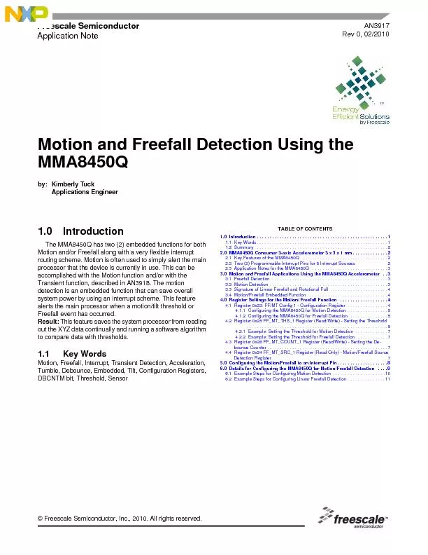
Motion and Freefall Detection Using the MMA8450Q by Kimberly Tuck Applications Engineer The MMA8450Q has two 2 embedded functions for both Motion andor Freefall along with a very flexible interrup ID: 504068

Motion and Freefall Detection Using

Share:

Link:

Embed:

Download Presentation from below link

Download Pdf The PPT/PDF document "freescale semiconductor inc 2010 all rig..." is the property of its rightful owner. Permission is granted to download and print the materials on this web site for personal, non-commercial use only, and to display it on your personal computer provided you do not modify the materials and that you retain all copyright notices contained in the materials. By downloading content from our website, you accept the terms of this agreement.


Presentation Transcript

© Freescale Semiconductor, Inc., 2010. All rights reserved.AN3917Rev 0, 02/2010Freescale Semiconductor Motion and Freefall Detection Using the MMA8450Q by: Kimberly Tuck Applications Engineer The MMA8450Q has two (2) embedded functions for both Motion and/or Freefall along with a very flexible interrupt routing scheme. Motion is often used to simply alert the main processor that the device is cu 1.1Key Words Motion, Freefall, Interrupt, TranTumble, Debounce, Embedded, Tilt, Configuration Registers, DBCNTM bit, Threshold, Sensor TABLE OF CONTENTS AN3917Freescale Semiconductor 1.2Summary A.The advantage of having two embedded functions to detect either Motion or linear Freefall which are routed to the choice of two interrupt pins allows for many combinations of events to be detected meeting the needs of many different use cases. For example: The embedded Motion/Freefall function can be used to detect a tumble using both the linear Freefall on one channel and the Motion detection to detect the spin on another channel.B.The status register for the Motion/Freefall function is only read when a change has occurred.C.Less processing is required on the microcontroller or processor with the embedded function since the condition is detected internally. The XYZ registers are not polled and data is not manipulated by the processor to detect the events.D.The threshold and debounce counter are changeable in either the active or standby mode to allow for adjustments after the part has transitioned from the wake to the sleep mode.E.Motion detection varies from Transient detection. The motion detection can trigger on a change in a static F.The latch will hold the EA bit until the status register is read to indicate an event is active, but the other bits in the status register are never latched. The status must be read immediately to determine the condition of the axes when an event occurs. 2.0MMA8450Q Consumer 3-axis The MMA8450Q has a selectable dynamic range of ±2g, ±4g and ±8g with sensitivities of 1024 counts/g, 512 counts/g and 256 counts/g respectively. The device offers either 8-bit or 12-bit XYZ output data for algorithm development. The chip shot anpinout are shown in Figure 1Figure 1. MMA8450Q Consumer 3-axis Accelerometer 3 x 3 x 1 mm 2.1Key Features of the MMA8450Q 1.Shutdown Mode: Typical A, Standby Mode 3 2.Low Power Mode current consumption ranges from 27 A (1.56 - 50 Hz) to 120 A (400 Hz) 3.Normal Mode current consumption ranges from 42 A (1.56 - 50 Hz) to 225 A (400 Hz) 4.I C digital output interface (operates up to 400 kHz Fast Mode) 5.12-bit and 8-bit data output, 8-bit high pass filtered data output 6.Post Board Mount Offset mg typical 7.Self Test X, Y and Z axes 2.2Two (2) Programmable Interr 1.Embedded 4 channels of Motion detection a.Freefall or Motion detection: 2 channels b.Tap detection: 1 channel c.Transient detection: 1 channel 2.Embedded orientation (Portrait/Landscape) detection with hysteresis compensation 3.Embedded automatic ODR change for auto-wake-up and return-to-sleep 4.Embedded 32 sample FIFO 5.Data Ready Interrupt 1 SCLINT2INT1SDASA0MMA8450Q 16PinQFN3mmx3mmx1mm AN3917 2.3Application Notes for the MMA8450Q The following is a list of Freescale Application Notes written for the MMA8450Q: AN3915Embedded Orientation Detection Using the MMA8450Q AN3916Offset Calibration of the MMA8450Q AN3917Motion and Freefall Detection Using the MMA8450Q AN3918High Pass Filtered Data and Transient Detection Using the MMA8450Q AN3919MMA8450Q Single/Double and Directional Tap Detection AN3920Using the 32 Sample First In First Out (FIFO) in the MMA8450Q AN3921Low Power Modes and Auto-Wake/Sleep Using the MMA8450Q AN3922Data Manipulation and Basic Settings of the MMA8450Q AN3923MMA8450Q Design Checklist and Board Mounting Guidelines Motion and Freefall Applications Using the MMA8450Q Accelerometer There are many applications that could potentially use Motion and/or Freefall. Some examples are the following: •Simpler motion signatures for gesturing (tilt thresholds, generic motions, linear freefalls •Human motion monitoring (specific parameters for motion and freefall) •Tamper detection on doors (detecting a threshold is exceeded or a change in tilt) •Shock detection or motion detection tracking assets (a threshold is exceeded) •Risk of an object falling: hard disk drives (linear freefall and motion) •Field meter monitoring for large motion/falls of the meters (tilt threshold change) 3.1Freefall Detection The Freefall function of the MMA8450Q detects linear freefall when X and Y and Z are below a set threshold. Typically this set threshold is below 0.35g. Although Freefall is often considered to be linear, this is often not entirely true in many fall use cases. Many falls can be tumbles which may cause the object to spin while falling. 3.2Motion Detection Motion detection can be used to alert that the device has exceeded a specific acceleration. This event could be due to a tilt odue to an acceleration that exceeds a value from a linear motion as shown Figure 2Figure 2. Motion Detection per Tilt or Linear AccelerationThe motion function can be used for detecting tumble. The signature of a tumble is shown in Figure 3. During the rotation of the tumble the magnitude of the three axes is much greater than 0g. In order to detect tumble, for example, the motion detectiocondition must be set to detect for X or Y or Z � 2g. It is also important to set the debounce counter to about 100 ms to avoidfalse readings. The debounce counter acts like a filter to determine whether the condition exists for 100 ms or longer. AN3917Freescale Semiconductor Figure 3. Rotational Freefall Signature 3.3Signature of Linear Freefall and Rotational Fall Figure 4, shows the signature of a Linear Freefall and a Rotational Fall. Both are falling events that require different conditions for detection. To be able to capture either a Linear Freefall or a Rotational Fall, the Motion/Freefall1 embedded function can used to detect the Linear Freefall while the Motion/Freefall2 can be used to detect the Rotational Fall (motion) or vise versa. Each function can be routed to the same interrupt pin or routed to separate interrupt pins.Figure 4. Fall Event Showing Linear and Rotational Fall 3.4Motion/Freefall Embedded Function The Motion function of the MMA8450Q compares the enabled X, Y, and/or Z-axis to determine if the acceleration output is greater than the set threshold. It does not compare a change in acceleration. Therefore, a tilt value could exceed the threshold to make this condition true. If an exact change in acceleration is the desired output the embedded transient detection can be uto configure the change in acceleration level for Motion detection. The transient detection eliminates the effects of gravity by pass-ing the data through a high pass filter to eliminate static accelerations. 4.0Register Settings for th There are four (4) registers associated with the Motion/Freefall embedded function.Note the Motion Freefall1 and the Motion/Freefall2 have the same configuration and functionality. 1.Register 0x23 FF/MT Config 1 - Motion/Freefall Configuration 2.Register 0x25 FF_MT_THS_1 - Setting the Threshold 3.Register 0x26 FF_MT_COUNT_1 - Setting the Debounce Counter 4.Register 0x24 FF_MT_SRC_1 - Motion/Freefall Source Detection Refer to Table 11 for the complete list of all registers that can be used with Motion/Freefall. AN3917 4.1Register 0x23: FF/MT Config The first register is the Motion/Freefall Configuration Register shown in Table 1. This register determines which axes to enable with regards to three (3) conditions: 1.Which axes will be involved, 2.Whether the event will be a linear freefall or a motion and, 3.Whether the event detected should be latched or not into the source register. 4.1.1Configuring the MMA8450Q for Motion DetectionFor Motion detection the condition should be set for the enabled axes to exceed the threshold. The logic will be an con-dition to make the condition true. The “high” condition bits should be enabled only, since Motion is detecting a (threshold condition. Therefore ZHEFE and are valid for Motion detection. Note the low condition bits such as and ZLEFE are not valid. In this example shown in Table 2. only the X and Y axes are considered.Example Code: IIC_RegWrite(0x23, 0xCA); //Enable Latch, Motion, X-axis, Y-axis4.1.2Configuring the MMA8450Q for Freefall DetectionFor Freefall detection the condition should be set so that the enabled axes have an acceleration value below) the threshold. The logic will be an condition to make the condition true. Note that all axes do not necessarily need to be enabled, but for a true freefall condition it is advised to set all three axes. In the Freefall Mode the ZLEFE and bits are valid. Note that the ZHEFE and XHEFE are not valid since they are used for Motion detection only. An example of linear freefall is shown in Table 3.Example Code: IIC_RegWrite(0x23, 0x95); //Enable Latch, Freefall, X-axis, Y-axis and Z-axis 4.2Register 0x25 FF_MT_THS_1 Register (Read/Write) - Sett The threshold for the event is set in Register 0x25, shown in Table 4. The minimum threshold resolution is dependent on the selected acceleration g range and the threshold register has a range of 0 to 127 counts. Therefore: •If the selected acceleration g range is 8g mode (= 11), the minimum threshold resolution is 0.063g/LSB. The maximum threshold is 8g. •If the selected acceleration g range is 4g mode (= 10), the minimum threshold resolution is 0.0315g/LSB. The maximum threshold is 4g •If the selected acceleration g range is 2g mode (FS = 01), the minimum threshold resolution is 0.01575g/LSB. The maximum threshold is 2g. Note: •For Motion detection the conditi�on is Threshold ( Figure 5 •For Freefall the condition is hreshold ( Figure 5 •All thresholds are absolute value. Table 1. Register 0x23: FF/MT Config 1 - Configuration Register (Read/Write) and DescriptionReg 0x23ELEOAEZHEFEZLEFEYHEFEYLEFEXHEFEXLEFE11001010Freefall 10010101Table 2. Motion Example 1: X or �Y 3gReg 0x23ELEOAEZHEFEZLEFEYHEFEYLEFEXHEFEXLEFE11001010Table 3. Freefall Example 1: X AND Y AND Z Reg 0x23ELEOAEZHEFEZLEFEYHEFEYLEFEXHEFEXLEFEFreefall 10010101Table 4. Register 0x25 FF_MT_THS_1 Register (Read/Write)Bit 7Bit 6Bit 5Bit 4Bit 3Bit 2Bit 1Bit 0DBCNTMTHS6 THS5THS4THS3THS2THS1THS0 AN3917Freescale Semiconductor Figure 5. Freefall Condition (Illustration)The bit is best understood from the diagram in Figure 6. The default value is for the counter to be in the increment/dec-rement mode.Figure 6. DBCNTM Bit Function (Illustration) X (Y, Z) High g RegionX (Y, Z) High g RegionX (Y, Z) Low g RegionHigh g+ ThresholdLow g ThresholdHigh g- Threshold-Full ScalePositiveAccelerationNegativeAcceleration Low g Event onCount ThresholdEA FF(Freefall)CounterValueLow g Event onCount Thresholdall 3-axis(Freefall)CounterValueLow g Event onCount ThresholdFF_MTEA FFall 3-axis(Freefall)CounterValueDBCNTM = 1EA FFDBCNTM = 0 AN3917 4.2.1Example: Setting the Threshold for Motion DetectionMotion Example 1: X or �Y 3gThe device must be in either 4g or 8g mode. Assuming the device is in 4g mode, therefore, the step count would be 0.0315g/LSB; therefore 3g/0.0315g = 95.2, which can be rounded to 96 counts. Note the threshold can be changed in either the Active or the Standby Mode. This may be useful for readjusting the threshold while in the active mode after an event has occurred. The bit will be kept cleared.Example Code: IIC_RegWrite(0x25, 0x60); //Set Threshold to 96 counts4.2.2Example: Setting the Threshold for Freefall DetectionFreefall Example 1: X AND Y AND Z In this example the device could be either 2g, 4g, or 8g mode. Assuming 2g mode, the step count is 0.01575g/LSB. Therefore 0.2g/0.01575g = 12.7, which rounds to 13 counts. Also for this example the DBCNTM bit will be kept cleared to filter out spurious noise.Example Code: IIC_RegWrite(0x25, 0x0D); // Set Threshold to 13 count 4.3Register 0x26 FF_MT_COUNT_1 Register (Read/Write) - Setting the Debounce Counter Register 0x26 shown in Table 5 is an 8-bit counter used for low pass filtering.The time step used for the debounce sample count depends on the ODR chosen. The relationship is shown inTable 6An ODR of 100 Hz and a FF_MT_COUNT_1 value of 10 would result in minimum debounce response time of 100 ms. Note: the debounce counter can be changed in the active or the standby mode. This may be desirable when the device changes from the wake mode to the sleep mode as the ODR may change. This will change the timing of the debounce counter.Example Code: IIC_RegWrite(0x26, 0x0A); // 100 ms debounce timing 4.4Register 0x24 FF_MT_SRC_1 RegisterDetection Register Register 0x24 shown in Table 7 keeps track of the acceleration events which trigger. The (Event Active) bit is used in com-bination with the INT_EN_FF_MT_1 bit (Register 0x3B) and INT_CFG_FF_MT_1 bit (Register 0x3C) to generate the Free-fall/Motion interrupt in register 0x15 (System Status Interrupt Register). Note: When the latch is enabled in Register 0x23 (Bit 7 ” bit, Bit 6 will remain set until the source register is read. Reading the source register clears the interrupt in Register 0x15 and clears the bit in Register 0x24.Table 5. Register 0x26 FF_MT_COUNT_1 (Read/Write)Bit 7Bit 6Bit 5Bit 4Bit 3Bit 2Bit 1Bit 0D7D6D5D4D3D2D1D0Table 6. FF_MT_COUNT_1 Relationship with the ODROutput Data Rate (Hz)StepDuration Range4002.5 ms2.5 ms – 0.637s2005 ms5 ms – 1.275s10010 ms10 ms – 2.55s5020 ms20 ms – 5.1s12.580 ms80 ms – 20.4s1.56640 ms640 ms – 163sTable 7. Events Detected in the Motion/Freefall Source Detection Register (Read Only) and LegendBit 7Bit 6Bit 5Bit 4Bit 3Bit 2Bit 1Bit 0—EAZHEZLEYHEYLEXHEXLE AN3917Freescale Semiconductor 5.0Configuring the Motion/Freef In order to set up the system to route to a hardware interrupt pin, the System Interrupt (Bit 1or 2 in Reg 0x3B) must be enableThe MMA8450Q allows for eight (8) separate types of interrupts. Two (2) of these are reserved for Motion/Freefall. There is onefor Motion/Freefall1 and one for Motion/Freefall2. For example, to configure the Motion/Freefall1 function, the following two steps should be followed.Step 1:Enable the Interrupt Bit 1 and/or Bit 2 in Register 0x3B shown in Table 8The corresponding interrupt enable bit allows the Motion/Freefall interrupt to route its event detection flag to the interrupt troller of the system. The interrupt controller routes the enabled function to the INT1 or INT2 pin. To enable the Freefall/Motion1 function, set Bit 2 in Register 0x3B as follows:Example Code: IIC_RegWrite(0x3B, 0x04);Step 2:Route the interrupt to INT1 or to INT2. This is done in register 0x3C shown in Table 9To set Motion/Freefall1 to INT1 set Bit 2 in register 0x3C.Example Code: IIC_RegWrite(0x3C,0x04); 5.1Reading the System Interrupt Status Source Register In the interrupt source register shown in Table 10 the status of the various embedded functions can be determined. The bits that are set (logic ‘1’) indicate which function has asserted an interrupt; conversely, the bits that are cleared (logic ‘0’) indicate which function has not asserted or has de-asserted an interrupt. The interrupts are rising edge sensitive. The bits are set by low to high transition and are cleared by reading the appropriate interrupt source register.Table 8. 0x3B CTRL_REG4 Register (Read/Write) – Interrupt Enable Description and LegendBit 7Bit 6Bit 5Bit 4Bit 3Bit 2Bit 1Bit 0INT_EN_ASLPINT_EN_FIFOINT_EN_TRANSINT_EN_LNDPRTINT_EN_PULSEINT_EN_FF_MT_1INT_EN_FF_MT_2 Table 9. 0x3C CTRL_REG5 Register (Read/Write)Bit 7Bit 6Bit 5Bit 4Bit 3Bit 2Bit 1Bit 0INT_CFG_ASLPINT_CFG_FIFOINT_CFG_TRANSINT_CFG_LNDPRTINT_CFG_PULSEINT_CFG_FF_MT_1INT_CFG_FF_MT_2Table 10. 0x15 INT_SOURCE: System Interrupt Status Register (Read Only)Bit 7Bit 6Bit 5Bit 4Bit 3Bit 2Bit 1Bit 0SRC_ASLPSRC_FIFOSRC_TRANSSRC_LNDPRTSRC_PULSESRC_FF_MT_1SRC_FF_MT_2 AN3917Freescale Semiconductor 6.0Details for Configuring the MMA The registers of importance for configuring the MMA8450Q for Motion detection or Freefall detection are listed in Table 11Table 11. Registers of Importance for Setting up the Motion/Freefall DetectionRegNameDefinitionBit 7 Bit 6Bit 5Bit 4Bit 3Bit 2Bit 1Bit 0 15 INT_SOURCE Interrupt Status SRC_ASLP SRC_LNDPRT SRC_PULSESRC_FF_MT_1SRC_FF_MT_2 SRC_DRDY FF_MT_CFG_1 FF/MotionConfig 1 ELE OAE ZLEFE YLEFE XHEFE XLEFE FF/MotionSource 1 ZHE XLE FF_MT_THS_1 FF/MotionThreshold 1 DBCNTM THS6 THS0 FF/MotionDebounce FF_MT_CFG_2 FF/MotionConfig 2 ELE OAE ZLEFE YLEFE XHEFE XLEFE FF/MotionSource 2 ZHE XLE FF_MT_THS_2 FF/MotionThreshold 2 DBCNTM THS6 THS0 FF/MotionDebounce 2 Control Reg4(Interrupt Enable Map) INT_EN _ASLP INT_EN _FIFO INT_EN _TRANS INT_EN_LNDPRT INT_EN_PULSEINT_EN_FF_MT_1INT_EN_FF_MT_2 Control Reg5 (Interrupt Configuration) INT_CFG_ASLP INT_CFG_FIFO INT_CFG_TRANS INT_CFG_LNDPRT INT_CFG_PULSEINT_CFG_FF_MT_1INT_CFG_FF_MT_2 AN3917Freescale Semiconductor 6.1Example Steps for Configuring Motion Detection X or Y �3g using MFF1Function 4g, 100 Hz ODR Step 1:Put the device into Standby Mode: Register 0x38 CtrlReg1IIC_RegWrite(0x38, 0x08); // Set the device in 100 Hz ODR, StandbyStep 2:Set Configuration Register for Motion Detection by setting the “OR” condition OAE = 1, enabling XHigh and YHigh and the latchIIC_RegWrite(0x23,0xCA)Step 3:Threshold Setting Value for the Motion detection of � 3g Note: In 4g mode each count is 31.5 mg •3g/0.0315g = 95.2; // Round up to 96 IIC_RegWrite(0x25, 0x60) Step 4:Set the debounce counter to eliminate false readings for 100 Hz sample rate with a requirement of 100 ms timer. 100 ms/10 ms (steps) = 10 countsIIC_RegWrite(0x26, 0x0A);Step 5:Enable Motion/Freefall1 Interrupt Function in the System (Ctrl Reg4) IIC_RegWrite(0x3B, 0x04);Step 6:Route the Motion/Freefall1 Interrupt Function to INT 1 hardware pin (CtrlReg5) IIC_RegWrite(0x3C, 0x04);Step 7:Put the device in 4g Active ModeIIC_RegWrite(0x38, 0x0A); //100Hz, 4g ModeStep 8:Write Interrupt Service Routine Reading the System Interrupt Status and the Motion/Freefall1 StatusInterrupt void isr_KBI (void)//clear the interrupt flagCLEAR_KBI_INTERRUPT;//Determine source of interrupt by reading the system interrupt IntSourceSystem=IIC_RegRead(0x15);// Set up Case statement here to service all of the possible interruptsif ((Int_SourceSystem &0x04)==0x04)//Perform an Action since Motion Flag has been set//Read the Motion/Freefall1 Function to clear the interruptIntSourceMFF1=IIC_RegRead(0x24);//Can parse out data to perform a specific action based on the //axes that made the condition true AN3917 6.2Example Steps for Configuring Linear Freefall Detection X AND Y AND Z .2g using MFF2Function 2g Mode, 50Hz ODRStep 1:Put the device in Standby Mode: Register 0x38 CtrlReg1 IIC_RegWrite(0x38, 0x0C); // Set the device in 50 Hz ODR, StandbyStep 2:Configuration Register set for Freefall Detection enabling “AND” condition, OAE = 0, Enabling XLow, YLow, ZLow, and the Latch IIC_RegWrite(0x27, 0x95);Step 3:Threshold Setting Value for the resulting acceleration gNote: In 2g mode each count is 15.75 mg •0.2g/0.01575 = 12.7 counts // Round up to 13 counts IIC_RegWrite(0x29, 0x0D); Step 4:Set the debounce counter to eliminate false positive readings for 50Hz sample rate with a requirement of 120 ms timer. Note: 120 ms/20 ms (steps) = 6 countsIIC_RegWrite(0x2A, 0x06);Step 5:Enable Motion/Freefall2 Interrupt Function in the System (Ctrl Reg 4)IIC_RegWrite(0x3B, 0x02);Step 6:Route the Motion/Freefall2 Interrupt Function to INT 2 hardware pin (CtrlReg5)IIC_RegWrite(0x3C, 0x00);Step 7:Put the device in 2g Active Mode, 50 HzIIC_RegWrite(0x38, 0x0D);Step 8:Write Interrupt Service Routine Reading the System Interrupt Status and theMotion/Freefall2 StatusInterrupt void isr_KBI (void)//clear the interrupt flagCLEAR_KBI_INTERRUPT;//Determine source of the interrupt by first reading the system interruptIntSourceSystem=IIC_RegRead(0x15);// Set up Case statement here to service all of the possible interruptsif ((IntSourceSystem&0x02)==0x02)//Perform an Action since Freefall Flag has been set//Read the Motion/Freefall2 Function to clear the interruptIntSourceMFF2=IIC_RegRead(0x28);//Can parse out data to perform a specific action based on the axes How to Reach Us:Home Page:www.freescale.comWeb Support:http://www.freescale.com/supportUSA/Europe or Locations Not Listed:Freescale Semiconductor, Inc.Technical Information Center, EL5162100 East Elliot RoadTempe, Arizona 852841-800-521-6274 or +1-480-768-2130www.freescale.com/supportEurope, Middle East, and Africa:Freescale Halbleiter Deutschland GmbHTechnical Information Center81829 Muenchen, Germany+44 1296 380 456 (English)+46 8 52200080 (English)+49 89 92103 559 (German)+33 1 69 35 48 48 (French)www.freescale.com/supportJapan:Freescale Semiconductor Japan Ltd.HeadquartersARCO Tower 15F1-8-1, Shimo-Meguro, Meguro-ku,Tokyo 153-0064Japan0120 191014 or +81 3 5437 9125support.japan@freescale.comAsia/Pacific:Freescale Semiconductor China Ltd.No. 118 Jianguo RoadChaoyang DistrictBeijing 100022China +86 10 5879 8000support.asia@freescale.comFor Literature Requests Only:1-800-441-2447 or +1-303-675-2140Fax: +1-303-675-2150LDCForFreescaleSemiconductor@hibbertgroup.comAN3917Rev. 002/2010Information in this document is provided solely to enable system and software implementers to use Freescale Semiconductor products. There are no express or implied copyright licenses granted hereunder to design or fabricate any integrated circuits or integrated circuits based on the information in this document.Freescale Semiconductor reserves the right to make changes without further notice to any products herein. Freescale Semiconductor makes no warranty, representation or guarantee regarding the suitability of its products for any particular purpose, nor does Freescale Semiconductor assume any liability arising out of the application or use of any product or circuit, and specifically disclaims any and all liability, including without limitation consequential or incidental damages. “Typical” parameters that may be provided in Freescale Semiconductor data sheets and/or specifications can and do vary in different applications and actual performance may vary over time. All operating parameters, including “Typicals”, must be validated for each customer application by customer’s technical experts. Freescale Semiconductor does not convey any license under its patent rights nor the rights of others. Freescale Semiconductor products are not designed, intended, or authorized for use as components in systems intended for surgical implant into the body, or other applications intended to support or sustain life, or for any other application in which the failure of the Freescale Semiconductor product could create a situation where personal injury or death may occur. Should Buyer purchase or use Freescale Semiconductor products for any such unintended or unauthorized application, Buyer shall indemnify and hold Freescale Semiconductor and its officers, employees, subsidiaries, affiliates, and distributors harmless against all claims, costs, damages, and expenses, and reasonable attorney fees arising out of, directly or indirectly, any claim of personal injury or death associated with such unintended or unauthorized use, even if such claim alleges that Freescale Semiconductor was negligent regarding the design or manufacture of the part. Freescale™ and the Freescale logo are trademarks of Freescale Semiconductor, Inc.All other product or service names are the property of their respective owners.© Freescale Semiconductor, Inc. 2010. All rights reserved.