/
ECEN 301 Discussion # ECEN 301 Discussion #

ECEN 301 Discussion # - PowerPoint Presentation

marina-yarberry
marina-yarberry . @marina-yarberry
Follow
349 views
Uploaded On 2020-01-18

ECEN 301 Discussion # - PPT Presentation

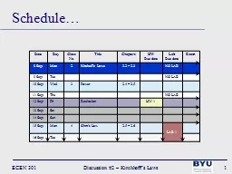
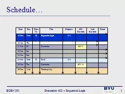
ECEN 301 Discussion 23 Sequential Logic 1 Date Day Class No Title Chapters HW Due date Lab Due date Exam 19 Nov Wed 23 Sequential Logic 141     20 Nov Thu             21 Nov Fri   ID: 773108

discussion ecen logic 301 ecen discussion 301 logic outputs sequential clock state flip change start inputs review flopsexample assuming

Share:

Link:

Embed:

Download Presentation from below link

Download Presentation The PPT/PDF document "ECEN 301 Discussion #" is the property of its rightful owner. Permission is granted to download and print the materials on this web site for personal, non-commercial use only, and to display it on your personal computer provided you do not modify the materials and that you retain all copyright notices contained in the materials. By downloading content from our website, you accept the terms of this agreement.


Presentation Transcript

ECEN 301 Discussion #23 – Sequential Logic 1 DateDayClassNo.TitleChaptersHWDue dateLabDue dateExam19 NovWed23Sequential Logic14.1  20 NovThu      21 NovFri RecitationHW 9 22 NovSat   23 NovSun      24 NovMon24DAC15.4 25 NovTueRecitationHW 1026 NovWedThanksgiving Schedule…

ECEN 301 Discussion #23 – Sequential Logic 2 Memory & CountersExodus 12:14  14 And this day shall be unto you for a memorial; and ye shall keep it a feast to the LORD throughout your generations; ye shall keep it a feast by an ordinance for ever. D&C 107:100  100 He that is slothful shall not be counted worthy to stand, and he that learns not his duty and shows himself not approved shall not be counted worthy to stand. Even so. Amen.

ECEN 301 Discussion #23 – Sequential Logic 3 Lecture 23 – Combinational & Sequential Logic

ECEN 301 Discussion #23 – Sequential Logic 4 Digital Logic Hierarchy2To4FADMemnmmIntelSequentialCombinationalGatesTransistorsProcessors

ECEN 301 Discussion #23 – Sequential Logic 5 Combinational Logic DecodersMultiplexers

ECEN 301 Discussion #23 – Sequential Logic 6 DecodersDecode the input and signify its value by raising just one of its outputs.A decoder with n inputs has 2n outputsXYZW2-to-4DecoderABWXYZDECODERSymbol

ECEN 301 Discussion #23 – Sequential Logic 7 DecodersWrite the truth tableXYZW

ECEN 301 Discussion #23 – Sequential Logic 8 DecodersWrite the truth tableXYZWABWXYZ001000010100100010110001

ECEN 301 Discussion #23 – Sequential Logic 9 MultiplexorsConnect one of its inputs to its output according to select signalsUseful for selecting one from a collection of data inputs.Usually has 2n inputs and n select lines.ABSC10MULTIPLEXOR Symbol

ECEN 301 Discussion #23 – Sequential Logic 10 MultiplexorsWrite the truth tableABSC10MULTIPLEXOR SymbolABSC000?001?010?011?100?101?110?111?

ECEN 301 Discussion #23 – Sequential Logic 11 MultiplexorsWrite the truth tableABSC10MULTIPLEXOR SymbolABSC00000010010101101000101111011111

ECEN 301 Discussion #23 – Sequential Logic 12 Sequential Logic

ECEN 301 Discussion #23 – Sequential Logic 13 Latches and Flip-Flops (FFs)Latch/FF: basic building block of memory devicesBistable devices – remain in one of 2 states (logic 0 or logic 1)Has 2 outputs (one is the complement of the other) – often only one is shown (the other is implied)Latches – imply that not controlled by a clockFFs – imply that they are controlled by a clockDQCLKTQCLKJQCLKKD - FFJK - FFT - FFSQRDQESQRED – Latch with enableSR – Latch with enableSR – Latch

ECEN 301 Discussion #23 – Sequential Logic 14 SR LatchSR Latch has 3 allowed states:Set (set Q to 1): S = 1, R = 0Reset (reset Q to 0): R = 1, S = 0Present state (keep Q as is): S = 0, R = 0 SR Latch has 1 illegal state:Instability (causes Q to switch between 0 and 1): S = 1, R = 1SRQQSQRSRQnew00Qold01010111XPresent stateResetSetIllegal

ECEN 301 Discussion #23 – Sequential Logic 15 SR LatchTiming diagram: a graph of inputs and outputs over time.TimeSRQFF is setFF is resetFF is again resetFF is setHOLDHOLDHOLDHOLDSRQnew00Qold01010111X

ECEN 301 Discussion #23 – Sequential Logic 16 SR LatchSR Latch with additional inputs:Enable (E) – S and R can only change Q when E is 1Preset (PRE) – regardless of S, R, or E, put Q to 1 when PRE is 1Clear (CLR) – regardless of S, R, E, or PRE, put Q to 0 when CLR is 1 SQREPRECLRESRPRECLRQPrecedence:If CLR = 1, Q = 0If PRE = 1, Q = 1If E = 1, Q is set based on SRIf S = 0 and R = 0, Q = holdIf S = 0 and R = 1, Q = 0If S = 1 and R = 0, Q = 1If S = 1 and R = 1, Q = unstableElse Q is heldSR can only change Q only in blue regions (where E = 1)

ECEN 301 Discussion #23 – Sequential Logic 17 D LatchD Latch has only 2 states:Set (set Q to 1): D = 1Reset (reset Q to 0): D = 0D Latch with enable (E):Q can only change when E = 1EDQnew00Qold01Qold100111DQESQREDEEDQD can only change Q only in blue regions (where E = 1)

ECEN 301 Discussion #23 – Sequential Logic 18 D Flip-FlopD FF: 2 SR latches in master/slave configuration. The output (Q) changes on the rising clock edgeDCLKQnew0011DQCLKSQRSQRQEECLKDQMasterSlaveCLKDQD can only change Q only on rising clock edge (arrows)“Edge-Triggered”

ECEN 301 Discussion #23 – Sequential Logic 19 JK Flip-FlopJK FF: 2 SR latches in master/slave configuration. The output (Q) changes on the falling clock edgeJKCLKQnew00Qold01010111QoldJK FF has 4 allowed states:Present state (keep Q as is): J = 0, K = 0 Reset (reset Q to 0): J = 0, K = 1Set (set Q to 1): J = 1, K = 0Toggle (set Q to Q): J = 1, K = 1SQRSQRQEECLKJQQKJQCLKKIndicates falling clock edge

ECEN 301 Discussion #23 – Sequential Logic 20 T Flip-FlopT FF: JK FF with J and K inputs connectedTCLKQnew0Qold1QoldT FF has 2 allowed states:Present state (keep Q as is): T = 0 Toggle (set Q to Q): T = 1CLKTQJQCLKKTQCLK

ECEN 301 Discussion #25 – Final Review 21 Flip-FlopsExample: Assuming the outputs of the following circuit start in a 000 state, determine the outputs for 4 clock cyclesCLKTQCLKJQCLKKDQCLKQ2Q1Q0

ECEN 301 Discussion #25 – Final Review 22 Flip-FlopsExample: Assuming the outputs of the following circuit start in a 000 state, determine the outputs for 4 clock cyclesCLKTCLKQnew0Qold1QoldDCLKQnew0011JKCLKQnew00Qold01010111Qold00000001110Set outputs to 000Based on output values change FF inputsOn each clock cycle: change FF outputs based on inputsChange FF inputs based on new outputsTQCLKJQCLKKDQCLKQ2Q1Q0

ECEN 301 Discussion #25 – Final Review 23 Flip-FlopsExample: Assuming the outputs of the following circuit start in a 000 state, determine the outputs for 4 clock cyclesCLKCycleQ2Q1Q0start000TCLKQnew0Qold1QoldDCLKQnew0011JKCLKQnew00Qold01010111Qold00000001110Inputs changed due to outputsTQCLKJQCLKKDQCLKQ2Q1Q0

ECEN 301 Discussion #25 – Final Review 24 Flip-FlopsExample: Assuming the outputs of the following circuit start in a 000 state, determine the outputs for 4 clock cyclesCLKCycleQ2Q1Q0start0001111TCLKQnew0Qold1QoldDCLKQnew0011JKCLKQnew00Qold01010111Qold11100001110Outputs change on new clock cycleTQCLKJQCLKKDQCLKQ2Q1Q0

ECEN 301 Discussion #25 – Final Review 25 Flip-FlopsExample: Assuming the outputs of the following circuit start in a 000 state, determine the outputs for 4 clock cyclesCLKCycleQ2Q1Q0start0001111TCLKQnew0Qold1QoldDCLKQnew0011JKCLKQnew00Qold01010111Qold11111110001Inputs changed due to outputsTQCLKJQCLKKDQCLKQ2Q1 Q 0

ECEN 301 Discussion #25 – Final Review 26 Flip-FlopsExample: Assuming the outputs of the following circuit start in a 000 state, determine the outputs for 4 clock cyclesCLKCycleQ2Q1Q0start00011112010TCLKQnew0Qold1QoldDCLKQnew0011JKCLKQnew00Qold01010111Qold01011110001Outputs change on new clock cycleTQCLKJQCLKKDQCLK Q 2 Q 1 Q 0

ECEN 301 Discussion #25 – Final Review 27 Flip-FlopsExample: Assuming the outputs of the following circuit start in a 000 state, determine the outputs for 4 clock cyclesCLKCycleQ2Q1Q0start00011112010TCLKQnew0Qold1QoldDCLKQnew0011JKCLKQnew00Qold01010111Qold01000101010TQCLKJQCLKKDQCLK Q 2 Q 1 Q 0 Inputs changed due to outputs

ECEN 301 Discussion #25 – Final Review 28 Flip-FlopsExample: Assuming the outputs of the following circuit start in a 000 state, determine the outputs for 4 clock cyclesCLKCycleQ2Q1Q0start000111120103100TCLKQnew0Qold1QoldDCLKQnew0011JKCLKQnew00Qold01010111Qold10000101010TQCLKJQCLKKDQCLK Q 2 Q 1 Q 0 Outputs change on new clock cycle

ECEN 301 Discussion #25 – Final Review 29 Flip-FlopsExample: Assuming the outputs of the following circuit start in a 000 state, determine the outputs for 4 clock cyclesCLKCycleQ2Q1Q0start000111120103100TCLKQnew0Qold1QoldDCLKQnew0011JKCLKQnew00Qold01010111Qold10010011000TQCLKJQCLKKDQCLK Q 2 Q 1 Q 0 Inputs changed due to outputs

ECEN 301 Discussion #25 – Final Review 30 Flip-FlopsExample: Assuming the outputs of the following circuit start in a 000 state, determine the outputs for 4 clock cyclesCLKCycleQ2Q1Q0start0001111201031004110TCLKQnew0Qold1QoldDCLKQnew0011JKCLKQnew00Qold01010111Qold11010011000TQCLKJQCLKKDQCLK Q 2 Q 1 Q 0 Outputs change on new clock cycle

ECEN 301 Discussion #23 – Sequential Logic 31 Digital CountersBinary up counter: with N bits, cycles through the numbers from 0 to 2N – 1A reset input will force the output to be zero N-bitBinary CounterBN-1B0B1B2…CLKReset3-bit up-counterCLKB0B1B2011010001000100101110111

ECEN 301 Discussion #23 – Sequential Logic 32 Digital CountersRipple counter: with N bits, cycles through the numbers from 0 to 2N – 1N JK FFs cascaded together to produce an N-bit up counterCLKJQCLKKJQCLKKJQCLKK111B0B1B2NB: for 3-bit counter we need 3 FFsCLKB0B1B2

ECEN 301 Discussion #23 – Sequential Logic 33 Digital CountersSynchronous counter: with N bits, cycles through the numbers from 0 to 2N – 1Input clock drives all FFs simultaneouslyTQCLKTQCLKTQCLKCLK1B0B1B2CLKB0B1B2

ECEN 301 Discussion #23 – Sequential Logic 34 RegistersRegister: an N-bit register is a cascade of N FFs to store data.Simplest type is a parallel input, parallel output registerRead/Write (WR) signal determines if data on the input is written to the FFsIf WR = 1 data is writtenDQCLKWRDQCLKWRDQCLKWRCLKRead/WriteQ0Q1QN-1D0D1D2RegisterNNCLKWR

ECEN 301 Discussion #23 – Sequential Logic 35 Simple Memory2-to-4Decodera1a000011011RegisterRegisterRegisterRegisterWRWRWRWRread/writed inputq outputThis is a functional view.The key parts are: address decoder memory cells (registers) output selector (mux)addressMemoryqnWRdmmMEMORY Symboln = 2addressq0q1q2q3addr