/
Impingement Jet Cooling on High Temperature plate Impingement Jet Cooling on High Temperature plate

Impingement Jet Cooling on High Temperature plate - PowerPoint Presentation

marina-yarberry
marina-yarberry . @marina-yarberry
Follow
405 views
Uploaded On 2017-05-05

Impingement Jet Cooling on High Temperature plate - PPT Presentation

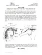
Boundary Layer Seminar Supervised by Dr Moghimi Student Arad Azizi Cooling a surface with an impinging liquid jet is an attractive technique because of its high efficiency and unsophisticated hardware ID: 544949

jet flow heat transfer flow jet transfer heat impingement nozzle region surface wall velocity high pressure number boundary temperature

Share:

Link:

Embed:

Download Presentation from below link

Download Presentation The PPT/PDF document "Impingement Jet Cooling on High Temperat..." is the property of its rightful owner. Permission is granted to download and print the materials on this web site for personal, non-commercial use only, and to display it on your personal computer provided you do not modify the materials and that you retain all copyright notices contained in the materials. By downloading content from our website, you accept the terms of this agreement.


Presentation Transcript

Slide1

Impingement Jet Cooling on High Temperature plate

Boundary Layer SeminarSupervised by Dr. MoghimiStudent: Arad AziziSlide2

Cooling a surface with an impinging liquid jet is an attractive technique because of its high efficiency and unsophisticated hardware

requirements.Such jets lend themselves to either convective boiling or to nonevaporative convection, but in both situations the cooling efficiency varies with radial distance from the point of

impact.Slide3
Slide4

Applications of impingement cooling are varied

processing of both metals and molded plasticscooling of high efficiency (aircraft) generator coils

cooling

of certain electronic modules

synchrotron X-ray, fusion, and

semiconductor laser

systems

Etc.Slide5

Compared with conventional convection cooling by confined flow parallel to (under) the cooled surface, jet impingement produces heat transfer coefficients that are

up to three times higher at a given maximum flow speed, because the impingement boundary layers are much thinner, and often the spent flow after the impingement serves to turbulate the surrounding

fluid.

Given the required heat transfer coefficient, the

flow required

from an impingement jet device maybe

two orders of magnitude smaller

than that required for a cooling approach using a

free wall-parallel flow

. For more uniform coverage over larger surfaces multiple jets may be

used.Slide6

Prior to the design of an impinging jet device, the heat transfer at the target surface

is typically characterized by a Nusselt number (Nu), and the mass transfer from the surface with a Schmidt number (Sc). For design efficiency studies and device performance assessment, these values are tracked vs. jet flow rate per unit area (G) or vs. the power required to supply the flow (incremental

compressor or pump

power).Slide7

Impingement Jet Regions

Initial free jetStagnationWall jetSecondary peakSlide8

The jet emerges from a nozzle or opening with a

velocity and temperature profile and turbulence characteristics dependent upon the upstream flow. For a pipe-shaped nozzle, also called tube nozzle or cylindrical nozzle, the flow develops into the parabolic velocity profile common to pipe flow plus a moderate amount of turbulence developed upstream

.

In contrast, a flow delivered by application of differential pressure across a thin,

flat

orifice (Slot Jet)

will create an initial flow with

a fairly flat velocity profile

, less

turbulence.Slide9

The

velocity gradients in the jet create a shearing at the edges of the jet which transfers momentum laterally outward, pulling additional fluid along with the jet and raising the jet mass flow. In the process, the jet loses energy and the velocity profile is widened in spatial extent and decreased in magnitude along the sides of the jet.Flow interior to the progressively widening shearing layer remains unaffected

by this momentum transfer and forms a core region with a higher total pressure, though it may experience a drop in velocity and pressure decay resulting from velocity gradients present at the nozzle exit.Slide10

As the flow approaches the wall, it loses axial velocity and turns. This region is labeled the

stagnation region or deceleration region. The flow builds up a higher static pressure on and above the wall, transmitting the effect of the wall upstream.Law of the wall at the wall jet region is not valid since there are pressure gradients effecting the flow on the wall from the upstream flow do not allow that the pressure gradients remain constant.Slide11

NONDIMENSIONAL HEAT AND MASS TRANSFER COEFFICIENTS

A major parameter for evaluating heat transfer coefficients is the Nusselt number.

The

nondimensional Sherwood number defines the rate of mass

transfer.Slide12

H/D : nozzle height to nozzle diameter ratio;

r/D : nondimensional radial position from the center of the jet;z/D : nondimensional vertical position measured from the wall;Tu :

nondimensional

turbulence intensity, usually evaluated at the nozzle;

Re0 : Reynolds number U_0 D/

ν;

M : Mach number (the flow speed divided by speed of sound in the fluid), based on nozzle exit average velocity (of smaller importance at low speeds, i.e. M<0.3);

pjet

/D : jet center-to-center spacing (pitch) to diameter ratio, for multiple jets;

Af

: free area (= 1-[total nozzle exit area/total target area]);

f : relative nozzle area (= total nozzle exit area/total target area).Slide13

Jet impingement devices have pressure losses from the other portions of the flow path, and part of the task of improving overall device performance is to reduce these other losses.

Nozzle Type

Initial Turbulence

Free Jet shearing Force

Pressure drop

Nozzle exit velocity profile

pipe

High

Low

High

Close to parabolic

Contoured contraction

Low

Moderate to high

Low

Uniform (flat)

Sharp orifice

Low

High

High

Close to uniform (contracting)Slide14

Jet behavior is typically categorized and correlated by its Reynolds number Re U_0

D/νAt Re<1000 the flow field exhibits laminar flow properties. At Re>3000 the flow has fully turbulent features.

A transition region occurs with 1000<Re<3000

.

Turbulence has a large effect on the heat and mass transfer rates.Slide15

Modeling of the turbulent flow, incompressible except for the cases where the Mach number is high, is based on using the well-established mass, momentum, and energy conservation equations based on the velocity, pressure, and

temperature.Slide16

The turbulent flow field along the wall may also cause formation of additional vortices categorized as secondary vortices. Turbulent fluctuations in lateral/radial velocity and associated pressure gradient fluctuations can produce local flow reversals along the wall, initiating separation and the formation of the secondary vortices, as shown in Figure. Secondary vortices cause local rises in heat/mass transfer rates and like the primary vortices they result in overall loss of flow kinetic energy and after they disperse downstream may cause local regions of lower transfer rate

.Slide17

ALTERNATE GEOMETRIES AND DESIGNS

The jet impingement angle has an effect on heat transfer and was studied often.Jet arrays with pulsed jets generate large-scale eddy patterns around the exit nozzle, resulting in unsteady boundary layers on the target that may produce higher or lower heat transfer coefficients, depending primarily on frequencies, dimensions, and jet Reynolds number. Slide18

Research Methods - EXPERIMENTAL TECHNIQUES

Impingement heat transfer experiments focus on measuring the flow field characteristics and the surface heat transfer coefficients. In an experiment a single jet or jet array is constructed and positioned above a solid target such as a plate or cylindrical surface. A pump or blower forces fluid onto the target plate while instrumentation collects information about fluid properties and target surface properties (LDV,PIV… techniques)

The temperature measurement is performed either by conventional temperature sensors at discrete locations, or for the entire surface at once by non-contact optical devices such as infrared (IR) radiometers, thermally sensitive paints, and frequently by

thermochromic

liquid crystals (TLC) that change their color with

temperature.Slide19

Research Methods - MODELING

Laminar ImpingementFor laminar flows in many geometries, the governing equations may be reduced to analytical solutions, such as that for a stagnating flow field placed above a wall boundary layer. Numerical modeling of steady laminar flows is fairly straightforward, using the mass, momentum and energy conservation equations in time-invariant forms

.Slide20

Research Methods - MODELING

Turbulent Impingement ModelsThe difficulties in accurately predicting velocities and transfer coefficients stem primarily from modeling of turbulence and the interaction of the turbulent flow field with the wall. The computation grid must resolve both the upstream and downstream flow around the nozzles or orifices and must extend sufficiently far to the side of a single jet or array (typically eight to ten diameters) to provide realistic exit conditions. Slide21
Slide22

Watson

applied a similarity transformation to solve the boundary layer equations for the case of a circular laminar free-surface jet impinging over a horizontal surface and derived expression for liquid film thickness in the radial flow region. The liquid film thickness can be determined asSlide23

Single-phase jet impingement heat transfer

Single-phase jet impingement cooling regime occurs when the surface temperature is below the temperature required for vapor bubble nucleation. In this regime, the heat transfer rate is governed by the Newton’s law of cooling.Slide24

For a laminar jet impinging on an uniformly heated flat surface, the following

formulas derived by Ma. et.al. for the Nusselt number distribution, have been explained.Region I (Impingement region,

)

Region

II

(

)

In this region, both the thickness of the viscous and thermal boundary layers are less than the liquid film thickness.

 Slide25

Region III

(

)

In this region, the thickness of the viscous boundary layer is equal to the film thickness but the thermal boundary layer is still smaller than the liquid film

.

Region IV

(

In this region, both the viscous and the thermal boundary layers have reached the liquid free-surface.

 Slide26

Multiphase Impingement due to high temperature heat fluxSlide27

Note: Boiling provides an efficient heat transfer mechanism for applications where heat transfer coefficients commonly exceed 10,000 W/(m^2 K) at relatively high heat fluxes. Slide28

Thank you for Your attention