/
Description of Operation Description of Operation

Description of Operation - PDF document

mitsue-stanley
mitsue-stanley . @mitsue-stanley
Follow
377 views
Uploaded On 2015-09-24

Description of Operation - PPT Presentation

GG 150 6 
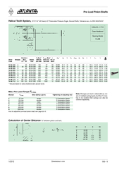
Preload pinion shafts consist of an output shaft a helical split pinion and a preload unit The split pinion is manufactured as a unit with an axial distance of s 1 mm m 24 an ID: 139361

6 Pre-load pinion shafts

Share:

Link:

Embed:

Download Presentation from below link

Download Pdf The PPT/PDF document "Description of Operation" is the property of its rightful owner. Permission is granted to download and print the materials on this web site for personal, non-commercial use only, and to display it on your personal computer provided you do not modify the materials and that you retain all copyright notices contained in the materials. By downloading content from our website, you accept the terms of this agreement.


Presentation Transcript

GG – 51/2015 Helical Tooth System, 19°31‘42” left hand, 20° Pressure Angle, Ground Teeth, Tolerance acc. to DIN 3962/63/67Max. Pre-Load Torque 67 Nmsingle Case-Hardened Pre-Load Pinion Shafts dwzbdkd3d2d1sb1b1lLL1 dwzhoao 74 92 3302 5080 83 030135673063.6667.73115254550 Dimensions in mm Dimensions in mmGG … 61/2012 Pre-load pinion shafts consist of an output shaft, a helical split pinion and a pre-load unit. The split pinion is manufactured as a unit with an axial distance of s = 1 mm (m = 2...4) and s = 2 mm (m = 5...8). By reducing the distance between the pinions (axidisplacement of the outer pinion) the backlash is reduced and pre-load initiated when teeth are in mesh with the rack. A de“nedpre-load torque between rack and split pinion can be produced by means of the pre-load unit.The pre-load unit consists of:UÊ>˜ÃŠ>`Ã•ÃƒÃŒˆ˜}ʘÕÌÊÜ…ˆV…ʈÃÊÃiVÕÀi`Ê>}>ˆ˜ÃƒÃŒÃŠÃŒÃ•Ã€˜ˆ˜}ÊLÞÊ“i>˜ÃƒÃŠœvÊ>ÊÃ>viÌÞÊÜ>Ã…iÀÊ>˜`Ê>Êcountersunk screwUÊ>Ê`ˆÃƒŽÃŠÃƒÂ«Ã€ˆ˜}Ê>ÃÃi“LÃžUÊ>ÊÌ…ÀÕÃÌÊ«>Ìi°The reverse side of the thrust plate is provided with 24 marks at m = 2...4 and 12 at 1. Determine the optimal tooth contact with non-preloaded split-pinion shaft. For this 2. The backlash between rack and split pinion should be 3. Tighten the adjusting nut (loosen the countersunk screw) until no backlash remains. by scanning the tooth ”anks with a dial indicator.4. The speci“ed degree of pre-load (T) can be produced by turning the adjusting nut The pre-load torque ŒT is the torque which ensures backlash-free positioning of the rack and pinion drive. The transmissible torque outside the positioning points ŒTcan be determined according to the following formula: the drive is free from play throughout the travelling distance. The pre-load is adjusted in assembled condition; therefore the front side of To adjust the pre-load, we recommend our adjusting wrench (page GG-8).Felt gearwheel or sliding brush with grease supply by means of an electronically controlled lubricator. Due to the elasticity of the teeth, the felt gearwheels can be used even with maximum backlash compensation.Pre-Load Pinion Shaft s mm / without Pre-Load Dimensions in mmGG … 71/2012 Pre-Load Pinion Shaft Adjusting Diagram for Pre-Load Torque T Dimensions in mmGG … 81/2012 Pre-Load Pinion Shaft … Adjusting Wrench74 90 001 74 92 330 19 8 12 10.0 2.5 37 50 27.5 0.113 74 92 430 74 93 320 74 93 420 74 93 520 74 94 51574 90 002 74 95 615 19 8 12 12.5 4.0 50 74 34.0 0.338 74 96 71374 90 003 74 98 612 22 9 12 13.0 6.0 67 96 40.0 0.625 74 98 712 Locking Screw of the Adjusting NutApply the adjusting wrench by hand.Be careful to position the adjusting wrench correctly in relation to the locking screw.The holding magnet holds the adjusting wrench in position.Loosen the locking screw by the adjusting nut.Use the Allen wrench with width over ”ats SWi or the fork wrench with width over ”ats SWa for turning the adjusting wrench.Tighten the locking screw by the adjusting nut.Order CodePre-Load TSWa la SWi li ds Lk d L 1/2012 Order Code T(Nm) d D L l G Shrink-Disk Clamping Sets For Output Drive Shafts of Gear Series HT, HP, E, B, BG and Gearwheels with Ground Teeth red Ji2 400 25 30 44 60.2 25.0 21.5 9.00 18.0 7 x M5 4 1.756 0.3 200 19 130 16 540 28 36 52 72.2 27.5 23.5 10.00 22.0 5 x M6 12 4.029 0.4 270 22 870 33 44 61 80.2 29.5 25.5 11.00 22.0 7 x M6 12 6.524 0.6 810 32 490 25 1350 38 50 72 90.2 31.5 27.5 12.00 22.0 9 x M6 12 11.322 0.8 1180 36 870 32 730 30 1480 44 55 75 100.2 34.5 30.5 13.00 23.0 8 x M6 12 18.729 1.1 810 35 630 32 2300 48 62 89 110.2 34.5 30.5 13.00 22.0 10 x M6 12 27.137 1.3 1420 40 1940 50 68 86 115.2 34.5 30.5 13.00 22.0 10 x M6 12 31.648 1.4 1490 45 3240 60 80 100 145.3 38.0 32.5 14.00 22.0 7 x M8 30 88.870 1.9 2580 55 80 80 110 7710 75 110 145 185.2 57.0 50.0 22.00 39.0 9 x M10 59 351.503 5.980 80 125 11080 85 125 160 215.3 61.0 54.6 23.00 42.0 12 x M10 59 664.000 8.3 270 20 24 36 50.2 23.0 19.5 7.60 14.0 5 x M5 5 0.780 0.280 83 130 280 25 30 44 60.2 21.5 18.0 7.25 14.0 7 x M6 12 1.756 0.380 84 136 430 28 36 52 72.2 25.5 21.5 9.10 17.5 5 x M6 12 4.029 0.480 85 150 950 36 50 70 90.2 28.0 24.0 10.25 22.0 9 x M6 12 11.322 0.8 ScrewTorque kg m² DescriptionThe series 24 cylindrical gears (pages ZA-24 to ZA-27 and ZB-21 to ZB-27) can be “tted on shafts (tolerance h7) either with key or with shrink plate “tting proceed as follows:Slide shrink plate onto cylindrical gear hub (do not tighten the screws before). Push the cylindrical gear on the shaft up to astop or the desired position. Now make the transverse pressure connection by uniformly tightening the clamping bolts. Tighten the bolts on after the other in several passes to the correct torque speci“ed in the table (do not tighten crosswise). Check thtorque with an indicating torque wrench.