/
VISHAY SEMICONDUCTORS Infrared Remote Control Receivers Application Note Vishays TSDP VISHAY SEMICONDUCTORS Infrared Remote Control Receivers Application Note Vishays TSDP

VISHAY SEMICONDUCTORS Infrared Remote Control Receivers Application Note Vishays TSDP - PDF document

mitsue-stanley
mitsue-stanley . @mitsue-stanley
Follow
614 views
Uploaded On 2014-12-22

VISHAY SEMICONDUCTORS Infrared Remote Control Receivers Application Note Vishays TSDP - PPT Presentation

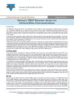
THE PRODUCTS DESCRIBED HEREIN AND THIS DOCUMENT ARE SUBJECT TO SPECIFIC DISCLAIMERS SET FORTH AT wwwvishaycomdoc91000 wwwvishaycom By John Fisher The TSDP series devices described in this application note ar e suitable for receiving lowspeed infrare ID: 27585

THE PRODUCTS DESCRIBED HEREIN

Share:

Link:

Embed:

Download Presentation from below link

Download Pdf The PPT/PDF document "VISHAY SEMICONDUCTORS Infrared Remote Co..." is the property of its rightful owner. Permission is granted to download and print the materials on this web site for personal, non-commercial use only, and to display it on your personal computer provided you do not modify the materials and that you retain all copyright notices contained in the materials. By downloading content from our website, you accept the terms of this agreement.


Presentation Transcript

VISHAY SEMICONDUCTORS Application Note Vishays TSDP Receiver Series forInfrared Data Communications APPLICATION NOTERevision: 27-Aug-14Document Number: 82666THIS DOCUMENT IS SUBJECT TO CHANGE WITHOUT NOTICE. THE PRODUCTS DESCRIBED HEREIN AND THIS DOCUMENTARE SUBJECT TO SPECIFIC DISCLAIMERS, SET FORTH AT www.vishay.com/doc?91000 www.vishay.comBy John FisherThe TSDP series devices described in this application note are suitable for receiving low-speed infrared data communications from 1200 bps to 9600 bps over a range of up to 35 meters using a single TSAL6200 infrared light emitting diode. The advantages of using infrared for this type of application are convincing; there is no government regulation of the infrared spectrum, the design is simple and fast, and the cost is low. This application note will help in successfully using these devicin your design.To achieve a high transmission range, a data communications system needs a high signal-to-noise (S/N) ratio. One way to improve S/N is to modulate the data signal with a carrier and then use band-pass filtering to exclude broadband noise, which falls outside the carrier frequency. The TSDP receiver series utilizes this technique, and includes devices that operate with carrier frequencies of either 38.4 kHz or 57.6 kHz.TSDP series devices differ from standard infrared receivers for remote control in several respects, including that their band-pfrequencies are tuned to the needs of RS-232 communication, and their pulse-width accuracy has been improved in order to maximize the highest possible data rate. Typical speeds for serial data communications are 9600 bps, 4800 bps, 2400 bps, etc. Inverting bps gives you seconds per bit, i.e. 104 µs for 9600 bps and 208 µs for 4800 bps. The minimum burst length for the TSDP series must be at least six full carrier cycles. Within these constraints, we can find the corresponding number of carriercycles per bit: six cycles at 57.6 kHz for 9600 bps, eight cycles at 38.4 kHz for 4800 bps, etc.OPTICAL NOISESince infrared light is a byproduct of creating visible light, many lamps, such as compact (CFL) or the backlighting of dimmed LCD panels, emit noise in the infrared spectrum. We mention these two noise sources since the frequency content of the noise they generate is near the pass-band of the TSDP receivers. A modulated noise is worse than a constant (DC) noise since the receivers are designed to receive modulated signals. To avoid receiving modulated noise, it must be distinguished from valid data signals in order to eliminate it while passing the valid signal. This is done using specially designed automatic gain control (AGC) circuits.The TSDP series includes two different AGC types: AGC1 and AGC3. Both of these AGC types can accept short bursts of six cycles or more. The criteria that AGC1 uses to distinguish noise are set rather leniently in order to better pass worst-case dapatterns (two particular data patterns are defined later as worst case). AGC1 can be used when it is known beforehand that there will be a relatively cleanŽ transmission medium, without noise from CFLs or LCD panels, which would have a high probability of creating spurious pulses at the output of the receiver. Usually cleanŽ means operating in an enclosed environment without such lighting, or outdoors.AGC3 applies more stringent criteria, and suppresses the noise from most types of CFLs and LCD panels. Such lamps are common in typical home, office, or factory settings. The side effect of effectively suppressing such noise is that certain datapatterns, if continuously sent, would also be unintentionally suppressed. We will therefore explore strategies to make use of the noise-suppressing AGC3 properties without triggering the AGC with our data.RS-232Before we discuss data transmission using the TSDP devices in more detail, let us define some terms. The TSDP series uses a form of digital modulation called amplitude shift keying (ASK). In fact, the devices use the simplest form of ASK, called on-ofkeying, which is in essence the presence or absence of a carrier. In the Morse code days, the presence of a carrier was called a mark,Ž either a dash or a dot. The name comes from the image, or mark, of a dash or dot on paper. The spaceŽ was the time between marks, i.e. the idle time of the carrier. Perhaps unfortunately, serial communication standards like RS-232 later defina mark not only as binary 1,Ž but also the idle time between data frames. A space was defined as binary 0.Ž In infrared data communications, just as with Morse code, we want to minimize the carrier on time to save power. In order to conform to RS-232 Vishays TSDP Receiver Series forInfrared Data CommunicationsAPPLICATION NOTE www.vishay.comVishay Semiconductors Revision: 27-Aug-14Document Number: 82666THIS DOCUMENT IS SUBJECT TO CHANGE WITHOUT NOTICE. THE PRODUCTS DESCRIBED HEREIN AND THIS DOCUMENTARE SUBJECT TO SPECIFIC DISCLAIMERS, SET FORTH AT www.vishay.com/doc?91000 standards, and in contrast to Morse code, a burst is only sent during an RS-232-defined space, or binary 0, and a mark is an idle time, or gap.Ž The terms space and burst will be used interchangeably in this paper, as will mark and gap.While RS-232 is not terribly efficient in using the available bandwidth, it is a format that can be readily understood by existing UART devices and is widely implemented, e.g. in the serial interface of PCs. In this protocol, data is usually sent in 8-bit chto create a character frame. Each eight bits of data is packed between one start bit (space) and usually one stop bit (mark) tocreate a 10-bit frame, and is transmitted one bit per clock cycle. Optionally, a parity bit may be inserted between the data anthe stop bit(s). An example of a typical frame is shown in the figure below.The following table shows which TSDP devices may be used for RS-232 data communications at several standard data rates. Note that devices appear in two columns. The first column is designated for AGC1 low-noise environments, and the second one for AGC3 typical-noise environments.One cell in this table represents a special case and is set apart with blue background: 4800 bps, 38.4 kHz, and AGC1. For this combination, any possible data pattern can be received indefinitely. In all other combinations in the table, data patterns existhat will trigger the AGC. Depending on the statistical prevalence of such data patterns, data transmission may need to be interrupted periodically to allow the AGC to recover. We now look at a theoretical explanation of why that is.Let us define two more terms: burst length (t) and envelope duty cycle (D). If we take an unvarying signal consisting of one burst and one gap that repeats indefinitely, then the burst length is simply the number of carrier cycles in the burst. The envelope duty cycle is the burst time divided by the burst repetition time: D = tFurther, let us note that modulated noise signals, such as the one depicted below from a CFL, have burst lengths and burst repetition times. Generally, different CFLs will have quite different characteristics. We will see in a moment how they interacwith AGC1 and AGC3. DATA RATE(bps) CARRIER FREQUENCY(kHz) CYCLES PER MARK / SPACE AGC1LOW-NOISEENVIRONMENTS AGC3TYPICAL-NOISEENVIRONMENTS960057.66TSDP34156, TSDP37156, TSDP36156TSDP34356, TSDP37356, TSDP36356480057.612TSDP34156, TSDP37156, TSDP36156480038.48 TSDP34138, TSDP37138, TSDP36138TSDP34338, TSDP37338, TSDP36338240038.416TSDP34138, TSDP37138, TSDP36138 0 1 2 3 4 5 6 7 mark spacedata bits bit( start tart B TB Vishays TSDP Receiver Series forInfrared Data CommunicationsAPPLICATION NOTE www.vishay.comVishay Semiconductors Revision: 27-Aug-14Document Number: 82666THIS DOCUMENT IS SUBJECT TO CHANGE WITHOUT NOTICE. THE PRODUCTS DESCRIBED HEREIN AND THIS DOCUMENTARE SUBJECT TO SPECIFIC DISCLAIMERS, SET FORTH AT www.vishay.com/doc?91000 AGC CHARACTERISTICSWe now create a space formed by plotting the burst length in number of cycles on the X axis vs. the envelope duty cycle on the Y axis. In the following diagram, we plot three types of meaningful data in this space: the AGC characteristic curves, the location of data signals, and the location of modulated noise signals. The AGC characteristic curves divide this space into three regionThe first zone, which is above the green curve, is called the AGC suppress horizon. Signals falling in this region will be suppressed by the AGC, and this is where we would like noise signals to lie. The second zone is below the purple curve, called the AGC accept horizon. Signals falling below this curve will always be passed by the AGC. The zone between the green and the purple curve is history-dependent, thereby forming a hysteresis area. If a signal moves from the suppress zone to the hysteresis zone, it remains suppressed. If a signal moves from the pass zone to the hysteresis zone, it remains passed. A suppressed signal in the hysteresis zone must first move to the pass zone before it can move back to the hysteresis zone and tB TB AGC1 Characteristics at f = 38.4 kHz AGC1 suppress horizon AGC1 pass horizon 8c burst 8c space0.10.20.30.40.50.60.70.80.9Envelope Duty Cycle020406080100120140Burst length [N cycles of carrier] Vishays TSDP Receiver Series forInfrared Data CommunicationsAPPLICATION NOTE www.vishay.comVishay Semiconductors Revision: 27-Aug-14Document Number: 82666THIS DOCUMENT IS SUBJECT TO CHANGE WITHOUT NOTICE. THE PRODUCTS DESCRIBED HEREIN AND THIS DOCUMENTARE SUBJECT TO SPECIFIC DISCLAIMERS, SET FORTH AT www.vishay.com/doc?91000 Also plotted on this diagram is the special case noted in our table above, with a light blue background: a data rate of 4800 bps, a 38.4 kHz carrier, spaces and marks both eight carrier cycles long (8c). We can identify two worst-case data patterns. The first of these patterns is alternating 1-0-1-0 etc. In this case, the burst length is just 8c, and the envelope duty cycle is 8c/(8c + 8c), or 0.5. This coordinate is plotted in the figure by the leftmost red dot.The second worst-case data pattern is when all data bits are 0, or bursts. In this case, we have a burst for the start bit plus eight bursts for the data, followed by a gap for the stop bit. Nine consecutive bursts give us 9 x 8c, or 72c, and the envelope duty cycle is (9 x 8c)/(10 x 8c) or 0.9. This coordinate is plotted in the figure by the rightmost red dot.All other data patterns fall in a region represented by the ellipse connecting the two red dots. Since the entire region falls the hysteresis zone, there exist no data patterns that trigger the AGC, and transmission using this format can continue indefinitely, no matter which data pattern is sent. Let us now look at two other cases from our table above. 9600 bps using 6c bits at 57.6 kHz is shown in the diagram below with red dots and a blue region, and 4800 bps using 12c bits at 57.6 kHz is shown with blue dots and a red region.Note that part of each of these regions overlap the suppress zone, thus there exist data patterns in each of these protocols thtrigger the AGC. If such patterns were to be sent repetitively, the data transmission would eventually be suppressed. In the caof 9600 bps, the overlap is on the left edge of the AGC curve. Characteristically for patterns off the left edge, there is a st mark pace tart toptart mark pace tart toptart AGC1 suppress horizon AGC1 pass horizon 6c space 6c mark 12c space 12c mark AGC1 Characteristics at f = 57.6 kHz0.10.20.30.40.50.60.70.80.9Envelope Duty Cycle020406080100120140Burst length [N cycles of carrier] Vishays TSDP Receiver Series forInfrared Data CommunicationsAPPLICATION NOTE www.vishay.comVishay Semiconductors Revision: 27-Aug-14Document Number: 82666THIS DOCUMENT IS SUBJECT TO CHANGE WITHOUT NOTICE. THE PRODUCTS DESCRIBED HEREIN AND THIS DOCUMENTARE SUBJECT TO SPECIFIC DISCLAIMERS, SET FORTH AT www.vishay.com/doc?91000 attenuation but not total suppression. This may not represent a significant hurdle in using these designs for several reasons. First, there are only a few data patterns out of 256 that result in AGC gain loss; the majority allow gain enhancement, which allows the AGC to recover. By monitoring the data as it is sent, the transmitter can easily detect when gain loss becomes critical - e.g. via repetitive transmission of gain loss bytes - and initiate a pause in the transmission to allow the AGC gain to recover. Second, some systems only require sporadic transmission of a small amount of data. In this case, a better understanding of how quickly, under worst-case conditions, the transmission could be suppressed would allow the system designer to create a robust system without any data monitoring necessary. We will return to this topic, but first let us examinthe properties of a more robust AGC.While AGC1 functions well in a completely undisturbed ambient, the more usual case is that some noise is present. AGC3, in contrast to AGC1, is designed to suppress many common types of ambient noise. The following chart plots the very same 38.4 kHz, 8c space and mark, 4800 bps signal that was plotted before. The AGC3 characteristic is now shown in solid green, and AGC1 in dashed green.With AGC1, continuous data transmission of any bit pattern using 8c per bit was possible. With AGC3 that is no longer the case;clearly some patterns now lie in the suppress zone. So why use it? On the same chart, we have now plotted regions in orange, which represent different noise patterns from CFL lamps and dimmed LCD panels. The reasoning behind the oddly shaped AGC curves now begins to emerge. In order to suppress these noise signals, they must lie in the suppress zone. But some of these noise patterns fall within the pass zone of AGC1, meaning the noise will be passed as if it were a valid signal and cause spurious pulses at the output of the receiver. AGC3s characteristic has been adjusted to ensure that these noise patterns really do lie in the suppress zone.A GENERAL RS-232 EXAMPLEA comprehensive understanding of the AGC characteristics allows us to assign an integer gain or loss value for each of the 256 possible bit patterns in any protocol. Since the receivers AGC operates at a fixed rate of gain change (approximately 100 dB/s) and the bit period is known, each transmitted bit pattern will correlate to a known changegain level. By summing this gain or loss value as each byte is transmitted, the transmitter can track the gain change at the receiver. Typically this change is zero, as random data usually will leave the gain at its maximum level. Only long strings of gain loss patterns will lower the gain to critical levels. 0.10.20.30.40.50.60.70.80.9Envelope Duty Cycle020406080100120140Burst length [N cycles of carrier] AGC3 suppress horizon AGC3 pass horizon AGC1 suppress horizon 8c space 8c mark AGC3 Characteristics at f = 38.4 kHz Vishays TSDP Receiver Series forInfrared Data CommunicationsAPPLICATION NOTE www.vishay.comVishay Semiconductors Revision: 27-Aug-14Document Number: 82666THIS DOCUMENT IS SUBJECT TO CHANGE WITHOUT NOTICE. THE PRODUCTS DESCRIBED HEREIN AND THIS DOCUMENTARE SUBJECT TO SPECIFIC DISCLAIMERS, SET FORTH AT www.vishay.com/doc?91000 The (semi) fixed variables of our system are the emitter intensity (I), the distance between Tx and Rx (d), the sensitivity of the receiver (Eemin.), and the ambient light. We will assume these are mostly under the control of the deom variable is the byte sequence that gets transmitted. Let us assume the transmission distance, d, must be 15 meters and that the Eemin.of the receiver given on the datasheet is 0.2 mW/m. The range, d, is related to emittethe equation d = Iemin.. Plugging in these values gives us the required emitter intensity I = (15) x 0.2 = 45 mW/sr. The intensity (in mW/sr) of a pulsed TSAL6200 infrared emitter is approximately linear with current (in mA) according to the equation I/0.6. So the forward current required to achieve this intensity is I = 45/0.6 = 75 mA.This is our baseline calculation without any margin. Let us now find the forward current required for a 3 dB margin according to the familiar 3 dB = 10 log(P), where P is the emitter power at the baseline, e.g. 45 mW/sr. Doing the math, P is then 90 mW/sr and the emitter forward current required to generate this is 90/0.6 = 150 mA. Using these values, we now have a system that can allow for 3 dB of gain loss due to transmission of loss bits before requiring the transmission to be interrupted. In practice one would build in a further margin to allow for component and other variations.In our example (38.4 kHz and 8c per bit), each bit is 208 µs long. At the AGCs rate of change (100 dB/s), it takes 144 bit timto lose 3 dB (144 x 208 µs x -100 dB/s = -3 dB). Therefore, if our running tally ever reaches minus 144 gain bits, then our receiver gain has reached its limit and we must temporarily interrupt the transmission to allow the AGC to recover.For further details on the relationship between bit patterns and loss bits, please contact the technical support link on our wewith the subject Data Transmission Loss Bits.ŽNON-RS-232 CODINGSUp to now, we have exclusively discussed RS-232-conforming transmission protocols, primarily because of their ease of incorporation into existing systems. If we are willing to depart from this standard, we stand to gain several benefits. These include better use of bandwidth - translating to a higher data rate - and noise suppression via AGC3, while at the same time maintaining continuous data transmission with no gain loss. The cost of these benefits to the system designer will be in providing some kind of interrupt and a timer fast enough to measure space and mark times, and writing their own encoder / decoder software.The protocol proposed below operates with a 57.6 kHz carrier, and transforms each 4-bit nibble into a single burst and gap. Both the burst length and the gap length contain information, and are modified to form one of 16 hexadecimal values. As a result of variable lengths, the transmission time per nibble is not constant, and the instantaneous data rate will vary depending on information content. The average period per nibble for this code is 514 µs, giving an average data rate of 7777 bits/s. It is standard practice to start an infrared transmission with a unique header, which should be long enough to allow the AGC to reach its steady state. Bursts of 6, 12, 18, and 24 cycles are all used to represent data and are not unique. A suitable choice would be to use the next longer burst length of 30 cycles (each burst differs by six cycles) followed by a 10-cycle gap.It is important while writing decoding software to understand that the output pulse width at the receiver has tolerances and can vary, for example, with changing input intensity at different ranges. The specification of interest is given in the datasheet as t - 1/f t + 4/f, where t is the input pulse width, t is the output pulse width, and f is the carrier frequency. This relationship says that the output pulse may be up to one carrier cycle shorter or up to four carrier cycles longer than the input pulse. Furthermore, the pulse-to-pulse jitter can also vary by as much as 2/f. Practical decoder designs require a dead-zone between bins, and we have designed our code such that gaps differ by 2/f. So in the table below, a dead-zone has been provided by calculating the minimum and maximum gap using 1.9/f Vishays TSDP Receiver Series forInfrared Data CommunicationsAPPLICATION NOTE www.vishay.comVishay Semiconductors Revision: 27-Aug-14Document Number: 82666THIS DOCUMENT IS SUBJECT TO CHANGE WITHOUT NOTICE. THE PRODUCTS DESCRIBED HEREIN AND THIS DOCUMENTARE SUBJECT TO SPECIFIC DISCLAIMERS, SET FORTH AT www.vishay.com/doc?91000 The logic is quite simple. Each burst is measured and evaluated for one of the four bins, and then the gap is measured and evaluated for one of the inner bins to determine the 4-bit nibble.Due to tolerances, the coding scheme presented will have a certain bit error rate of about 10. This is not ultra-reliable, but sufficient for many applications. There is a trade-off between data rate and bit error rate. If a higher bit error rate is required and a lower data rate can be tolerated, it is a simple matter to widen the bins to ensure that device tolerances are well within the bin limits. The author wishes to thank Thomas Mistele and Anika Kühnle for their technical support in preparing this document. HEX BURST CYCLES GAP CYCLES TOTAL CYCLES TOTAL(µs) MIN. BURST(µs) - 1/f MAX. BURST(µs) (µs)gap - 1.9/f (µs)gap + 1.9/f00000610162788717414120710001614203478717421027620010618244178717428034530011622284868717434941540100626325568717441848450101630366258717448855460110121022382191278141207701111214264511912782102768100012183052119127828034591001122234590191278349415A1010122638660191278418484B1011181028486295382141207C1100181432556295382210276D1101181836625295382280345E1110241034590399486141207F1111241438660399486210276 000118c/18c110112c/22c1001 Vishays TSDP Receiver Series forInfrared Data CommunicationsAPPLICATION NOTE www.vishay.comVishay Semiconductors Revision: 27-Aug-14Document Number: 82666THIS DOCUMENT IS SUBJECT TO CHANGE WITHOUT NOTICE. THE PRODUCTS DESCRIBED HEREIN AND THIS DOCUMENTARE SUBJECT TO SPECIFIC DISCLAIMERS, SET FORTH AT www.vishay.com/doc?91000 INTERFACING WITH UARTSThe fact that the receivers output pulse width has tolerances with respect to the input signal also has repercussions when interfacing with UARTs. Typical practice in UART receiver design is to use an internal clock and counter that operate at 16 timthe bit rate for sampling the incoming data. The counter is reset at the beginning of each start bit. Typically a UART samples the bit state, high or low, at the middle of the bit time, or after 8 of its internal clock cycles. It is therefore essential when interfacing the IR receiver directly with a UART that the worst case pulse distortion in the IR receiver does not violate adjacent bit readings in the UART. To clarify, when a burst (IR receiver output low) is followed by an idle (output high) the receiversoutput must transition to high before the mid-point of the following bit. To avoid data errors, the width of any single pulse must never extend to half of a bit time into the following idle bit. For a protocol with 6 carrier cycles per bit, the critical upper limit is + 3/f. For an 8 carrier cycle per bit protocol, the corresponding limit is t + 4/fThere are two receiver specifications of interest. The first, general specification, t - 1/f t + 4/f is given in the figure below and does allow output pulses up to the critical limit of 4/f. This specification states that under some manufacturing tolerances and conditions of use, output pulses may be up to 1 carrier cycle shorter, or by up to 4 carrier cycles longer than corresponding input pulses. Neither of the examples discussed so far, 6 cycle bits or 8 cycle bits, can reliably function over this entire range of tolerances without additional, pulse shortening, circuitry or software. I.e., shorting the pulses by 1.5/f is one solution to moving the specification back into conformity with the UARTs requirements.The second specification of interest is in the electrical characteristics, maximum pulse width of 11.5/f for 8 cycle bits and e min.&#x -6.;瀀 10 mW/m. What this says is that if the signal strength is sufficient, either via a higher power emitter or a smaller distance between emitter and receiver, the pulse width of the receiver will be shorter than t + 3.5/f, thus also fulfilling the UARTs requirements. Note in the following diagrams that pulse width is a function of signal strength. For a fixed emitter intensity, pulse width approaches its nominal value as the distance between emitter and receiver is rethat at a fixed distance, the pulse width approaches its nominal value as the emitter power is increased. In other words, pulsewidth is no more an independent characteristic of an infrared receiver than its maximum reception distance. Both depend on the power generated by the IR emitter. 0.1110100 typical sample TSDP34138 receiving adata pattern with N = 8 carrier cycles emitter intensityIe = 100 mW/sr shortest pulse among 1000 pulses longest pulse among 1000 pulses 0.1110100 typical sample TSDP34156 receiving adata pattern with N = 6 carrier cycles emitter intensityIe = 100 mW/sr shortest pulse among 1000 pulses longest pulse among 1000 pulses