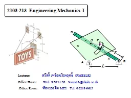
/
1 ENGINEERING MECHANICS GE 107 1 ENGINEERING MECHANICS GE 107

1 ENGINEERING MECHANICS GE 107 - PowerPoint Presentation

myesha-ticknor
myesha-ticknor . @myesha-ticknor
Follow
343 views
Uploaded On 2019-06-23

1 ENGINEERING MECHANICS GE 107 - PPT Presentation

Lecture 6 Introduction Bodies differ from particles as their dimensions are not neglected Bodies can be classified as rigid bodies resistant bodies and deformable bodies A  rigid body ID: 760067

Share:

Link:

Embed:

Download Presentation from below link

Download Presentation The PPT/PDF document "1 ENGINEERING MECHANICS GE 107" is the property of its rightful owner. Permission is granted to download and print the materials on this web site for personal, non-commercial use only, and to display it on your personal computer provided you do not modify the materials and that you retain all copyright notices contained in the materials. By downloading content from our website, you accept the terms of this agreement.


Presentation Transcript

Slide1

1

ENGINEERING MECHANICS

GE 107

Lecture 6

Slide2

Introduction

Bodies differ from particles as their dimensions are not neglectedBodies can be classified as rigid bodies, resistant bodies and deformable bodies.A rigid body is an idealization of a solid body of finite size in which deformation is neglected. A rigid body can be considered as a combination of a large number of particles in which all the particles remain at a fixed distance from one another, both before and after applying a load.This model is important because the material properties of any body that is assumed to be rigid will not have to be considered when studying the effects of forces acting on the body.In most cases the actual deformations occurring in structures, machines, mechanisms and the like are relatively small and the rigid-body assumption is suitable for analysis.

2

Slide3

Introduction (Contd..)

3

Hook – as an example of particle assumption

Rail road wheel –rigid body

Slide4

UNIT II EQUILIBRIUM OF RIGID BODIESSYLLABUS

Moments and Couples – Moment of a force about a point and about an axis –Vectorial representation of moments and couples – Scalar components of a moment –Varignon’s theoremFree body diagram – Types of supports and their reactions – requirements of stable equilibrium Equilibrium of Rigid bodies in two dimensions Equilibrium of Rigid bodies in three dimensions Examples

4

Slide5

Cartesian Vector Formulation for Moment

Considering the coordinate axes x, y and z. then the position vector r and force F can be expressed as Cartesian vectors.

Applying cross product equation

where rx , ry, rz represent the x, y, z components of the position Vector from point O to any point on the line of action of the force and Fx ,Fy, Fz represent the force components of the force vector.

5

Slide6

Resultant Moment of Forces

If a body is acted upon by a system of forces as shown in Fig.,

the resultant moment of the forces about point O can be determined by vector addition of the moment of each force. This resultant can be written symbolically as

6

Slide7

Principle of Moments

A concept often used in mechanics is the

principle of moments, which is sometimes referred to as Varignon’s TheoremIt was originally developed by the French mathematician Varignon (1654- 1722).It states that the moment of the of force about a point is equal to the sum of the moments of components of the force about that point. This theorem can be shown by the distribution law of cross product.Considering the forces shown in Fig.,As Therefore

7

Slide8

Moment of a Force about a

Specified Axis

Some times-the moment produced by a force about a specified axis must be determined. For example, suppose the lug nut at a on the car tire as in Fig. needs to be loosened. The force applied to the wrench will create a tendency for the wrench and the nut to rotate about axis passing through 0But the nut can only rotate about the y axis.Hence only the y component of the moment is needed and the total moment produced is not important. To determine this component, we can use either a scalar or vector analysis.

8

Slide9

Moment of a Force about a Specified Axis (Contd..)

Scalar Method

To use a scalar analysis in the case of the lug nut as in Fig.,the moment arm (perpendicular distance ) from the axis to the line of action of the force is dy = d cos . Thus. the moment of F about the y axis is My=Fdy= F(d cos ). According to the right-hand rule. My is directed along the positive y axis as shown in the figure. In general, about any axis a, the moment is

9

Slide10

Moment of a Force about a Specified Axis (Contd..)

Vector Method

To find the moment of force F about the y

axis using a vector analysis, we must first determine the moment of

the force about the

point 0 on the y axis by applying Equation

Mo = r X F.The component My along the y axis is the projection of Mo on the y axis. It can be found using equation of dot product M y= j · Mo= j . (r X F). where j is the unit vector for the y axis.Let ud be the unit vector along any axis a, thenThe result can be written in the matrix form as

10

Slide11

Problem 1

Determine the moment M

AB produced by the force F in Fig.a, which tends to rotate the rod about the AB axis.

11

Slide12

Solution to Problem 1

12

Scalar method cannot be applied as find the perpendicular distance is difficult.

Using Vector method

Where

u

B

is the unit vector along AB which can be found as

r

B

is the position vector from A to B

the coordinates for point B is (4,2,0 ) and that of A is (0,0,0)

Vector r in the moment equation is a vector directed between any point on line AB to the line of action of force F

Slide13

Solution to Problem 1 (Contd.)

13

It can be the vector

r

C

or rD also.Considering the coordinates for point D from A.The force is

Slide14

Solution to Problem 1 (Contd..)

14

Slide15

Problem 2

Determine the magnitude and direction of moment of force F about segment OA

15

Slide16

Solution to Problem 2

To get the force in vector form ,

find the unit vector along OA

Find the position vector for force segment OA

Hence the moment about OA is

16

Slide17

Moment of a Couple

A couple is defined as two parallel forces that have the same magnitude but opposite directions and are separated by a perpendicular distance ‘d’.

17

Slide18

Moment of a Couple (Contd..)

For example, imagine that you are driving a car with both hands on the steering wheel and you are making a turn.

One hand will push up on the wheel while the other hand pulls down, which causes the steering wheel to rotateSince the resultant force is zero, the only effect of a couple is to produce a rotation or tendency of rotation in a specified direction. This is nothing but a moment or moment of a coupleThe moment produced by a couple can be called as Couple Moment.

18

Slide19

Couple Moment -Scalar Formulation

19

The moment of a couple as shown in the Fig. is defined as having

a magnitude ofWhere F is the magnitude of one of the forces and d is the perpendicular distance or moment arm between the forces. The direction and sense of the couple moment are determined by the right hand rule, where the thumb indicates this direction andthe fingers are curled with the sense of rotation caused by the couple forces. In all cases, M will act perpendicular to the plane containing the forces.

Slide20

Couple Moment – vector Formulation

20

Moment can be determined by finding the sum of the moments of both couple forces about any arbitrary point.

For example as in Fig. the position vectors rA and rB are directed from point 0 to points A and B lying on the line of action of - F and FThe couple moment determined about 0 isBut the position vectors are added asHenceThis result indicates that a couple moment is a free vector i.e., it can act at any point since M depends only upon the position vector r directed between the forces.

Slide21

Resultant Couple Moment

Since couple moments are vectors, their resultant can be determined by vector addition.

For example, consider the couple moments M

1 and M2 acting on the pipe as shown in the Fig.a.Since each couple moment is a free vector, we can join their tails at any arbitrary point and find the resultant couple moment as shown in Fig.b.MR=M1+M2If more than two couple moments act on the body, we may generalize this concept and write the vector resultant as

21

Slide22

Problem 3

Determine the magnitude and direction of the couple moment acting on the gear as shown in the Figure. (R.C. Hibbeler p151)

22

Slide23

Solution to Problem 3

Scalar Approach

The distance d can be found graphically and substituting in the formula M= Fd , its magnitude can be foundAnalytical method to find d is complicated and hence vector approach is used

23

Slide24

Solution to Problem 3 (Contd..)

The forces are resolved in to two components

The moments of respective resolved components are found about any point (say O) Summing up the moments will give the resultant couple moment caused by the forcesThis positive result indicates that M has a counter clock wise rotational sense and it is directed outward . perpendicular to the board.

24

0.2 m

600 sin30

N

600 sin30

N

M

1

0.2 m

600 cos30

N

600 cos30

N

M

2

Slide25

Problem 4

Replace the two couples acting on the pipe column as shown in the figure by a resultant couple moment.

25

Slide26

Solution to Problem 4

Let the couple moments M

1 and M2 are produced by the forces F1 and F2 respectivelyWhere F1 = 150 N and F2= 125 NThe vector M1 is given as

26

Slide27

Solution to Problem 4 (Contd..)

The vector M

2

is computed in the similar manner as

The resultant moment is thus

27

Slide28

Simplification of Force and couple system

28

Slide29

Example

29

Slide30

Example (Contd.)

30

Slide31

Problem 5

31

Find the resultant moment for the system shown

Slide32

Single Equivalent Force

Analysis of any system requires simplificationA system acted upon by many forces and couples can be first converted in to single resultant force and single resultant moment system.This can be further reduced into a single equivalent force system

32

Slide33

Single Equivalent Force (Contd.)

For a concurrent system, in which the lines of action of all the forces intersect at a common point O, the force system produces no moment about this point.

As a result, the equivalent system can be represented by a single resultant force FR .

33

Slide34

Single Equivalent Force (Contd.)

For a coplanar system of force the lines of action of all the forces lie in the same plane. So the resultant force of this system also lies in this plane.Furthermore, the moment of each of the forces about any point 0 is directed perpendicular to this plane. Thus, the resultant moment MR and resultant force FR will be mutually perpendicular.The resultant moment can be replaced by moving the resultant force FR to a perpendicular or moment arm distance d away from point 0 such that FR produces the same moment MRO about point O. This distance d can be determined from the scalar equation (MR)o = FRd

34

Slide35

For the parallel force system as shown in Figure, forces are parallel to the y axis. Thus, the resultant force FR at point 0 must also be parallel this axis. The moment produced by each force lies in the plane o f the plate, and so the resultant couple moment, MR. will also lie in this plane along the moment axis a, since FR and MR o are mutually perpendicular. As a result, the force system can be further reduced to an equivalent single resultant force F, acting through point P located on the perpendicular b axisThe distance d along the b axis from point 0 requires

35

Single Equivalent Force (Contd.)

Slide36

If there is a distributed force system as shown in the figures below

For case shown above, the uniformly distributed load 6kN/m can be represented by a single force whose magnitude equals to magnitude of the UDL times the length along which it is distributed And its position would be middle of the length along which it is distributedFor the loading shown, it is 6 X 6=36 kN

36

Single Equivalent Force (Contd.)

36

kN

Slide37

For the variably distributed loading shown in Figure below:

The single force representation can be obtained asThe magnitude of the equivalent force is equal to the area of the triangle formed by the VDL which is ½ ( b X h)the length along which it is distributed And its position would be at the centroid of triangle which is 1/3 h

37

Single Equivalent Force (Contd.)

Slide38

Problem 6

Determine the resultant force and specify where it acts on the beam measured from A .(Ans: 24.75 kN and 2.59 m)

38

Slide39

Free Body Diagram

A complete understanding of all the known and unknown external forces for the successful application of the equilibrium equations is required The best way to account for these forces is to draw a free-body diagram.This diagram is a sketch of the outlined shape of the body, which is isolated from its surroundings (free body).It also shows all the forces and moments that the surroundings exert on the body.

39

Slide40

Support Reactions

A body will have six degrees of freedom in spaceWhen ever it is constrained or restricted to move it will produce reactions (forces)If it is not allowed to translate it will produce forces andIf the rotation is restricted, it will give rise to momentsA support may arrest some of the rotations and/ or translations and hence it produces reactive forces and moments

40

Slide41

Support Reactions in 2D

Roller Support –restricts translation in y direction–reaction force developed in y directionHinged or Pinned Support – restricts translations in x as well as y direction – reaction forces developed in x as well as y directionFixed Support – restricts translations in x and y direction and also the rotation .– reaction forces developed in x and y direction and a reactive moment developed .

41

Slide42

42

Support Reactions (Contd..)

Slide43

Support Reactions (Contd..)

43

Slide44

Support Reactions (Contd..)

44

Slide45

Support Reactions (Contd..)

45

Slide46

Reactions in 3D

Z

Y

X

Z

Y

X

Z

X

Y

Find the constraint

forces and moments

for the

given

a

ssembly

and show them in the FBD

FBD of 1

FBD of 2

F

X

F

Z

F

Y

F

Z

F

Y

F

X

M

Y

M

Z

M

Y

M

Z

As the shaft system is free to move in one direction only (rotate around

X),

it has five constraints namely

Fx

,

Fy

,

Fz

,

M

Z

and M

y

.

Slide47

Exercises

Problem 1

Problem 2

Problem 3

Problem 4

Slide48

Problem 6

Draw the Free body diagram of beam

48

Slide49

Problem 7

49

Two smooth

pipes

each having a mass of 300 kg. arc supported by

the forked

tines of the tractor as in Fig. Draw the free body diagrams for each pipe and both pipes together

Slide50

Condition For Equilibrium

The force and couple moment system acting on a body can be reduced to an equivalent resultant force and resultant couple moment at any arbitrary point O on or off the body.lf this resultant force and moment are both equal to zero, then the body is said to be in equilibrium. i.e.,

50

Slide51

Condition For Equilibrium (Contd..)

When applying the equations of equilibrium, it is assumed that the body remains rigid. In reality, all bodies deform when subjected to loadsMost engineering materials such as steel and concrete are very rigid and so their deformation is very small. When applying the equations of equilibrium, it is generally assumed that the body will remain rigid and not deform under the applied load.Hence the direction of the applied forces and their moment arms with respect to a fixed reference remain unchanged before and after the body is loaded.

51

Slide52

Problem 8

52

Determine the reactions on

the beam