/
Copyright 2003 Kilowatt Classroom, LLC. Motor Control Motor Overload P Copyright 2003 Kilowatt Classroom, LLC. Motor Control Motor Overload P

Copyright 2003 Kilowatt Classroom, LLC. Motor Control Motor Overload P - PDF document

myesha-ticknor
myesha-ticknor . @myesha-ticknor
Follow
678 views
Uploaded On 2015-09-17

Copyright 2003 Kilowatt Classroom, LLC. Motor Control Motor Overload P - PPT Presentation

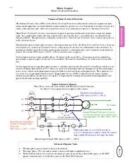
Sheet 1 System Protection OL0 Purpose of Motor Overload Protection The National Electric Code NEC defines Motor Overload Protection as that which is intended to protect motors motorcontrol appa ID: 131792

Sheet System Protection OL0

Share:

Link:

Embed:

Download Presentation from below link

Download Pdf The PPT/PDF document "Copyright 2003 Kilowatt Classroom, LLC. ..." is the property of its rightful owner. Permission is granted to download and print the materials on this web site for personal, non-commercial use only, and to display it on your personal computer provided you do not modify the materials and that you retain all copyright notices contained in the materials. By downloading content from our website, you accept the terms of this agreement.


Presentation Transcript

Sheet 1 Copyright 2003 Kilowatt Classroom, LLC. Motor Control Motor Overload Protection System Protection OL0 Purpose of Motor Overload Protection The National Electric Code (NEC) defines Motor Overload Protection as that which is intended to protect motors, motorcontrol apparatus, and motor branch-circuit conductors against excessive heating due to motor overloads and failure of the motor to start. Motor Overload Protection is also commonly referred to as “Running Protection”. Note: Motor Overload Protection is not intended to protect against motor branch-circuit short-circuit and ground faults. In a combination starter, this type of protection is provided by fuses, a circuit breaker, or a Motor Circuit Protector (MCP). This protection is commonly referred to as “Short Circuit Protection” and is shown circled in red in the schematic below. Fractional horsepower single-phase motor overload protection may be by: the Branch Circuit Protection, a Separate Overload Device, an Integral Thermal Protector, or Impedance Protected, or a combination of these methods, de-pending on whether or not the motor is permanently installed, is continuous-duty, and is manually or automatically started. Refer to the NEC Articles 430.32 - 430.34 for details and exceptions. Overload protection for single and three-phase AC motors in the small (above 1 horsepower) and medium horse-power range is typically provided by one of two methods: Thermal Overload Relays, or Solidstate Overload Re-lays Overload protection for large three-phase motors is sometimes provided by Thermal Overload Relays which are con-nected to Current Transformers (CT’s). However, most new installations utilized microprocessor-based motor pro-tective relays which can be programmed to provide both overload and short-circuit protection. These protective re-lays often also accept inputs from Resistance Temperature Devices (RTD’s) imbedded in the motor windings (usually two per phase) and the relays are capable of displaying the winding and motor bearing temperatures, and provide both alarm and trip capability. Schematic Diagram Notes · The three-phase power circuit is shown in bold black. · The single-phase 120 volt control circuit is shown with light-weight black lines. · The bold black dashed lines indicate a mechanical connection and show that all three poles of the MCP operate simultaneously as do the three poles of the Main (M) Contactor . Motor Branch-Circuit Short-Circuit and Ground Fault Protection. NEC Articles 430.51 - 430.58 Motor Overload Protection NEC Articles 430.31 - 430.44 High temperature on overload heater due to excessive current opens control circuit OL contact, dropsout the M contactor, and stops the motor. Motor Control Circuit NEC Articles 430.71 - 430.74 Typical Schematic Diagram ThreePhase Across-Line Starter with Thermal Overload Protection See Sheet 5 for an operational description of this circuit. M FU3 X1 X2 120 VAC Control Circuit 1 2 3 FU1 FU2 OL OL OL MOTOR L1 L2 L3 MCP START OL M Ma STOP Integral Thermal Protector/s (if used) are inside motor and sense motor wind-ing temperature. See NEC Article 430.32 To Control Sheet 2 Copyright 2003 Kilowatt Classroom, LLC. Motor Overload Protection Thermal Overload Blocks System Protection OL1 Overload Heaters Assortment of various types. Two units on left are eutectic alloy type, other three are for bimetallic overload blocks. Heater on left incorporates ratchet wheel and alloy barrel into heater element. Eutectic Alloy Type Center phase heater shown removed. On this style of overload block the heater can be mounted in one of four possible positions for fine adjustment of the trip value. Each position places the heater in a slightly different proximity to the melting alloy barrel. The heater has a pointed position indicator tab which shows the selected mounting orientation. Pointed Heater Position Tab Eutectic Alloy Barrel (Heater Removed) Overload Reset Push Button Overload Contact Connection Terminal Overload Heater - Shown in installed position. Overload heaters work on principle that motor load (and therefore motor temperature) is directly related to the current drawn by the motor. Current flowing from the motor contactor to the motor passes through the motor overload heaters (one per phase) which are mounted in the control overload block. If the motor current exceeds the desired value, the heat produced by the motor overload heater will cause a control circuit contact in the overload block to open, drop out the contactor coil, and stop the motor. Manufacturers provide Heater Selec-tion Charts from which the correct heater is chosen based on the motor nameplate Full Load Amps (FLA). Bimetallic Type Shown Plugged into Bottom of Contactor Overload Heaters One per phase Overload Contact Terminals One side of OL contact is factory wired to coil terminal (red wire). Reset Push Button Calibration Adjustment Varies OL trip setting from 85% - 115% of heater table value. Wire spring position sets OL unit for manual or automatic reset. Factory installed coil jumper from overload contact (red wire). Motor “T-Lead” Connections at bottom of each heater. Ratchet Wheel Overload Heater Schematic Symbol Sheet 3 Copyright 2003 Kilowatt Classroom, LLC. Motor Overload Protection Thermal Relay Operation System Protection OL2 Melting Alloy Type Overload Contact Opening Spring POWER FROM CONTACTOR CONTROL POWER FROM CNTL TRANSFORMER X2 Heater Element Ratchet Wheel Pawl NormallyClosed (NC) Overload Contacts Operating Principle The term eutectic means “easily melted”. The eutectic alloy in the heater element is a material that goes from a solid to liquid state without going through an intermediate putty stage. When the motor current exceeds the rated value, the temperature will rise to a point where the alloy melts; the ratchet wheel is then free to rotate, and the contact pawl moves upward under spring pressure allow-ing the control circuit contacts to open. After the heater element cools, the ratchet wheel will again be held stationary and the overload contacts can be reset. Severe fault currents can damage the heater element and they should be replaced after such an occurrence. However, normal overloads, usually, will not affect the heater element or alter its accuracy. Motor Starting (MS) Switch Designed to protect small single-phase motors. Mounts in standard switch box. Switch Box Mounting Ears OnOff Toggle Switch Plugin Heater Overload Heater Power from Contactor Bimetallic Strip Bends downward. ToggleType Spring Contact Normally closed, snaps open (up) when pushed down by insulated spacer. Bimetallic Type Overload NC Overload Contact In motor control circuit. Insulated Spacer. Pushes contact open. Motor T Lead Connection Stationary Contact Sheet 4 System Protection Copyright 2003 Kilowatt Classroom, LLC. Motor Overload Protection Typical Heater Selection Chart How to Use the Overload Selection Chart Shown below is an overload chart for Cutler Hammer, Citation Line Starters. Assume you have an Enclosed Type C300, NEMA Size 2 Starter, and that the motor nameplate FullAmps (FLA) is 11.0 amps. For this example you will use TABLE ST-3. Look down the TABLE ST-3 column until you find the heater range that includes the FLA for your motor and then look across to the Heater Coil Catalog Number column to select the correct heater. Sheet 5 Copyright 2003 Kilowatt Classroom, LLC. Schematic Diagram Phase Across-Line Starter Motor Control MC1 Schematic Diagram STOP START OL M Ma FU3 X1 X2 120 VAC Control Circuit 1 2 3 M FU1 FU2 OL OL OL MOTOR L1 L2 L3 MCP Circuit Description In the schematic above, the three-phase power circuit is shown in bold lines and the single-phase control circuit is shown by a lighter weight line. This circuit employs a standard START/STOP push button station and is know as a Three Wire Control Scheme because it requires three wires (shown numbered above) from the push button station to the other control components. · For safety, this circuit uses a standard single-phase control transformer to provide low voltage (120 VAC) control and the X2 bushing is normally grounded. CAUTION: Some systems do not have a grounded X2! (This is sometimes done for continuity of service reasons - so that a control system ground will not shut the system down.) · The transformer primary is connected downstream of the Motor Circuit Protector (MCP) so that when the motor control is turned off, the control circuit will also be de-energized - another important safety feature. · After the fuse, the first control component is the STOP button. · The normally closed Overload Contact is placed on the X2 side of the Main Contactor Coil M. · Additional STOP push buttons are always wired in series, and additional START push buttons are always wired in parallel. Circuit operation is as follows: · Close MCP to apply power to the circuit. · Depress momentary START push button. This causes the Main Contactor Coil M to be energized. · Main Contactor Coil M closes M contacts (3) to start motor and also closes the Ma auxiliary contact. · Auxiliary Contact Ma seals around the momentary START push button which can now be released. · The motor continues to run until the normally closed STOP push button is momentarily depressed. · In the event of an overload, the overload heaters will open the normally closed OL contact and drop-out the Main Contactor M and stop the motor. · After an overload trip, the overload heaters must cool to permit resetting of the overload contact.