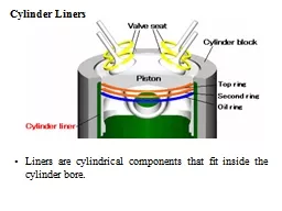
/
Cylinder Liners Liners are cylindrical components that fit inside the cylinder bore. Cylinder Liners Liners are cylindrical components that fit inside the cylinder bore.

Cylinder Liners Liners are cylindrical components that fit inside the cylinder bore. - PowerPoint Presentation

myesha-ticknor
myesha-ticknor . @myesha-ticknor
Follow
377 views
Uploaded On 2018-10-23

Cylinder Liners Liners are cylindrical components that fit inside the cylinder bore. - PPT Presentation

Purpose of liners Liners are provided in order to increase the service life of the engine ie wear resistant surface for bore It simplifies the production of cast iron engines Material used Liners are made of cast iron and special alloys of iron containing silicon manganese nickel and chr ID: 694164

valve piston dead rings piston valve rings dead center cylinder exhaust rod top connecting oil steel opens liners liner

Share:

Link:

Embed:

Download Presentation from below link

Download Presentation The PPT/PDF document "Cylinder Liners Liners are cylindrical c..." is the property of its rightful owner. Permission is granted to download and print the materials on this web site for personal, non-commercial use only, and to display it on your personal computer provided you do not modify the materials and that you retain all copyright notices contained in the materials. By downloading content from our website, you accept the terms of this agreement.


Presentation Transcript

Slide1

Cylinder Liners

Liners are cylindrical components that fit inside the cylinder bore.Slide2

Purpose of liners:

Liners are provided in order to increase the service life of the engine i.e., wear resistant surface for boreIt simplifies the production of cast iron engines

Material used:

Liners are made of cast iron and special alloys of iron containing silicon, manganese, nickel and chromium.

There are two types of liners

Dry liner

and

Wet linerSlide3

Dry liner

It is in the form of a barrel having flange at the top which fits in the grooves of block. It is not directly in contact with water. Hence it is called dry liner. It is machined from both the sides.

Wet liner

It is in the form of barrel shape provided with flange at top which fits into the grooves of the cylinder block.

Grooves are provided to cylinder or liner. Rubber packings are inserted into the bottom grooves.

These are having direct contact with water. Hence called as wet liners.

Machining from both the sides are not required because it does not bear against the cylinder block.Slide4
Slide5

Comparison of dry liners with wet liners

Sl. No.Description

Dry Liners

Wet Liners

1.

Contribution

of rigidity of cylinder block

More rigidity

Less rigidity

2.

Introduction of thermal barrier at the adjoining surfaces

More

Less

3.

Cooling

Inferior

Better

4.

Renewal after wear

Comparatively difficult

Easy

5.

Chances of coolant leakage

Less

More Slide6

PISTONSlide7
Slide8
Slide9

Functions of a Piston

To transmit the force of explosion to the crankshaftTo form a seal for high pressure gasses in the combustion chamber do not escape into the crankcase

To serve as a guide and a bearing for small end of the connecting rodSlide10

Piston must satisfy the following conditions

Silent in operation

Rigidity for high pressure

The design should be such that seizure does not occur

Resistant to corrosion due to some products of combustion e.g. sulphur dioxide

It should have shortest possible length so as to decrease overall engine size

Lighter in weight so that inertia forces created by its reciprocating motion are minimized

High thermal conductivity for efficient heat transfer so that higher compression ratios may be obtained without the occurrence of detonation Slide11
Slide12

Top of the piston is called

head or crown Some pistons head is provided valve relief.

Pistons used in some high powered engines may have raised domes, which increases compression ratio as well as controls the Combustion.

In some engines pistons may be specially dished to form the desired shape of the combustion chamber. Slide13

Piston ‘Skirt’

The part of the piston below the rings is called ‘Skirt’.Its function is to form a guide suitable for absorbing the side thrust produced on account of the inclination of the connecting rod.

It must be of sufficient length to resist tilting of the piston under load.

The combustion pressure from the piston crown is transmitted to the connecting rod through the ‘webs’ inside the piston.

The webs also form heat path from the piston crown to the gudgeon pin bosses and the skirt. The ‘Bosses’ form a bearing surface for the rocking motion of the connecting rod. Slide14

Piston Materials

Common materials used are cast iron, cast aluminium, forged aluminium, cast steel, forged steel and alloys of aluminium.

Cast iron is the ideal material for rubbing surfaces of piston.

Cast iron and steel have the high strength required for good wearing qualities at required temperature and low thermal expansions.

But heavier pistons than aluminium and low thermal conductivity

Aluminium alloy pistons have the advantage of low weight and high thermal conductivity which makes it to run cool.

But it is less strong and hence thicker sections have to be used. Slide15

Since it is softer fine particles of lubricating oil get embedded on it. Piston life gets shortened due to abrasion

Expansion is about 2.5 times that of the cast iron Strength also reduces as temperature rises

Due to unequal coefficient of expansion from the cylinder if large cold clearance is kept the ‘piston slap’ would occur.Slide16

To prevent heat from the piston skirt following methods are adoptedBy providing horizontal slot

By providing inclined slot in the oil ring groove

By making a heat dam

By vertical slot

By T-slot

By tapered piston

Using special alloys

Wire wound pistons

Autothermic piston

Bi-metal piston

Aeconoguide pistonSlide17
Slide18
Slide19

Wire wound pistons:A band of steel wire under initial tension is put between the

piston pin and the oil control ring, thus restricting the expansion of the skirt .

Autothermic piston:

This type of piston contains low thermal expansion steel insert at the piston pin bosses. These inserts are so moulded that their

ends are anchored in the piston skirt as shown

.Slide20

Bi-metal piston:In this type of piston skirt is formed by steel and the aluminium alloy cast inside it forms piston head and piston pin bosses.

As the coefficient of thermal expansion for steel is quite small, the piston will not expand much and hence smaller cold clearances can be maintained.Aeconoguide piston:

This is a method to reduce skirt friction. The skirt contact area is reduced by about 75% compared to conventional pistons.

And consist of raised pads which are specially shaped to assist the hydrodynamic lubrication.Slide21

Piston head designs Slide22

Piston Failures

Scuffing

Scoring

Burnt Piston

Worn out Circlip groove

Damaged piston pin boss

Damaged Ring landSlide23

Scuffing :

This occurs due to excessive heat, the piston expands and becomes tight in the cylinder. As a result lubricant is squeezed out from the cylinder walls and metal to metal contact takes place. Scoring:

Piston is scored as a result of carbon build-up

.

Accumulation of carbon and other deposits on the piston skirt. Particles of carbon breaking away

from the exhaust ports, lodging between the piston skirt and cylinder results in scoring the piston.

Damage to Ring land:

This occurs mainly because excessive ring groove clearance and

attempting to remove the piston without first removing the cylinder ridge.

Damage to piston pin boss and circlip groove:

This occurs rocking motion of the connecting rod due to bent connecting rod or tapered crankpins or loosely installed circlip

Piston FailuresSlide24

PISTON RINGS

These are circular rings and made of special steel alloys which retain elastic properties even at high temp.

These are housed in the circumferential grooves of piston outer surface

Main

function of the piston ring is to impart the necessary radial pressure to maintain the seal between piston and the cylinder bore. Slide25

It prevents gas leakage into the crank case. It has contacts with cylinder walls evenly and tightly fit into the grooves.

It is made by fine grained cast iron. Modern rings are made by steel.Types

of piston rings:

Compression rings or Pressure rings

Oil control rings or Oil scraper rings

The compression rings are located at the top portion of the piston.

Two or three compression rings are fitted in order to increase the compression ratio and one or two oil rings to remove the excess oil from the cylinder walls.Slide26

Functions of compression rings

To seal between the piston and the cylinder liner.To transfer the

heat

To

absorb piston

fluctuations due to side thrust.

Any

number of piston rings.

The heat transfer is better from rings to the

liner.

It is better to use a number of narrow rings than a few wide shallow rings.Slide27

Types of rings and groovesSlide28

Functions of oil control rings

To scrape the lubricating oil from the surface of the liner. During the upward stroke these should allow sufficient oil to go upwards for the proper lubrication of the liner.Slide29

Types of piston ring Ends

Butt cutAngle

cut

Square step cut

joint or Lap

Round step cut jointSlide30

CONNECTING ROD

Manufactured by drop forgingShould have adequate strength, stiffness with minimum weightMaterial

Shape of connecting rod:

Rectangular

Circular

Tubular

I-section

H-sectionSlide31

Connecting Rod

There are 2 types of small end

and big end bearings

Split

at right angle to its length

Split a

t

an angle Slide32

Connecting

Rod AssemblySlide33

Cross Section of Connecting

RodSlide34

Crank ShaftSlide35
Slide36

The Front end of the crankshaft carries three devices- gear or sprocket that drives the camshaft, vibration damper to control torsional vibration and the fan belt pulley.

Rear end of the crankshaft carries fly wheel.Crank shaft have drilled oil passages through which oil can flow from the main bearings to the connecting rod bearingSlide37

ValvesSlide38

Valve is a device to admit the Air-Fuel mixture and expel gases from cylinder.

Inlet valve is made by

Nickel Chromium alloy steel

and Exhaust valve is made by

Silichrome steel

.

The face of the valve should be ground to make an angle

45

0

to 30

0

in order to match the angle of valve seat in the head or block.

Valves used in modern vehicles are treated as mushroom valves.

There are two types of valve mechanisms namely

“Straight mushroom valve mechanism” and

“Overhead mushroom valve mechanism”Slide39

Overhead Valve MechanismSlide40

As crank shaft rotates, cam shaft rotates will also rotates there by rotating cams mounted on it. Cams lift the push rod by valve lifter.

Push rod actuates the rocker arm and opens the valve. Valves are mounted in the cylinder head and valve clearance is in between rocker arm and valve stem.Slide41

Straight Mushroom Valve MechanismSlide42

When the crank shaft rotates cam shaft rotates, valve lifter slides up and down due to rotation of cams.

When the valve lifter moves upwards valve stem moves upward which operates the valves. Valve mechanism is provided in the engine block. Here valve clearance is between valve stem and valve lifterSlide43

Valve Timing diagram

EVO

EVC

IVO

IVC

Valve OverlapSlide44

To see how valve-timing works in a 4-stroke engine cycle, let’s show piston motion as a circle. In this simple cycle, each stroke is shown as a semi-circle.

The intake valve opens at top dead center, and closes at bottom dead center. The blue line shows that period and it matches the intake stroke.

The exhaust valve opens at bottom dead center, then closes at top dead center before the new air-fuel mixture enters the cylinder.

In practice, the intake valve usually opens earlier than top dead center, and stays open a little past bottom dead center.

The exhaust valve opens a little before bottom dead center, and stays open a little past top dead center.

When the valves actually open and close, can be measured by angles. To make these angles easier to read, let’s use a

spiral

instead of a circle.Slide45

This intake valve opens 12° before the piston reaches top dead center.

And it closes 40° after bottom dead center.The exhaust valve opens 47° before bottom dead center - and stays open - until 21° past top dead center. This gives exhaust gases more time to leave.By the time the piston is at 47° before bottom dead center on the power stroke, combustion pressures have dropped considerably and little power is lost by letting the exhaust gases have more time to exit.

When an intake valve opens before top dead center and the exhaust valve opens before bottom dead center, it is called

lead.

When an intake valve closes after bottom dead center, and the exhaust valve closes after top dead center, it is called lag.

On the exhaust stroke, the intake and exhaust valve are open at the same time for a few degrees around top dead center. This is called valve

overlap.

On this engine, it is 33°.

Different engines use different timings. Manufacturer specifications contain the exact information. Slide46

Port Timing Diagram

(TDC)

(BDC)

IPO

IPC

EPO

EPCSlide47

Exhaust Port opens before piston reaches BDC and after sometime inlet valve opens. During next stroke of the piston, first inlet valve closes then exhaust valve closes. After exhaust port closes compression of fuel-air mixture takes placeSlide48