/
Grant holder, ELSA Laboratory, Joint Research Centre of the European C Grant holder, ELSA Laboratory, Joint Research Centre of the European C

Grant holder, ELSA Laboratory, Joint Research Centre of the European C - PDF document

myesha-ticknor
myesha-ticknor . @myesha-ticknor
Follow
409 views
Uploaded On 2016-03-16

Grant holder, ELSA Laboratory, Joint Research Centre of the European C - PPT Presentation

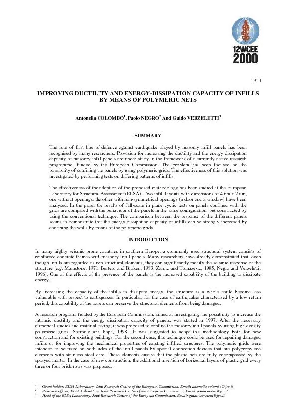
1910As a part of the research programme both material testing and fullscale confirmation tests were conducted withthe aim of assessing the proposed technique as well as of providing the necessary d ID: 257477

1910As part the

Share:

Link:

Embed:

Download Presentation from below link

Download Pdf The PPT/PDF document "Grant holder, ELSA Laboratory, Joint Res..." is the property of its rightful owner. Permission is granted to download and print the materials on this web site for personal, non-commercial use only, and to display it on your personal computer provided you do not modify the materials and that you retain all copyright notices contained in the materials. By downloading content from our website, you accept the terms of this agreement.


Presentation Transcript

Grant holder, ELSA Laboratory, Joint Research Centre of the European Commission, Email: antonella.colombo@jrc.itResearch officer, ELSA Laboratory, Joint Research Centre of the European Commission, Email: paolo.negro@jrc.it 1910As a part of the research programme, both material testing and full-scale confirmation tests were conducted, withthe aim of assessing the proposed technique as well as of providing the necessary data for the calibration of thenumerical models to be used in the following parametric analyses.In the current research practice there are two approaches to the infilled frame modeling: refined models of thenonlinear Finite Element type and phenomenological Macro models (typically of the equivalent diagonal struttype). For engineering practice macromodels are more suitable, since they are computationally efficient and mostappropriate for nonlinear seismic response analyses of complete structures. Accordingly, considerable effort hasbeen devoted by many authors [e.g. Klingner and Bertero, 1976; Panagiotakos and Fardis, 1994; Zarnic, 1994;Combescure and Pegon, 1996] to the development, calibration and computer implementation of such models.The main parameters of the multilinear loading curve to be identified are those that determine the location of thecracking and ultimate strength. The slope of the post-ultimate softening branch and the residual strength, alsoimportant in order to better represent the behavior of panels, are usually more difficult to identify. This fact ismainly due to the impossibility to extract, from the available test results, the contribution of the surroundingframe.Important information regarding the strength degradation of panels was also obtained from the tests. Inparticular, the modifications caused by the strengthening of the panels on the envelope curve describing theseismic behavior of masonry infills, is discussed in details.DESCRIPTION OF THE EXPERIMENTAL ACTIVITYThe effectiveness of the proposed provisions has been investigated by performing full-scale in-plane cyclic tests.The behaviour of solid infills and infills with non-symmetrical openings (Figure 1) has been analysed. It wasdecided to re-use a three-storey steel frame already available at the ELSA Laboratory. The panels wereconstructed on the ground floor (dimension 4.60m x 3.15m) of the two parallel frames on a 0.55m high concretebase in order to preclude any influence of the stiffeners at the base of the columns. With the aim of furtherreducing the contribution of the frame to the behaviour of the panels, the columns were partially cut at both ends. Fig. 1: Layout of the panels (dimensions in mm).The same bricks used in previous experiments carried out at the ELSA Laboratory were used. They werevertically perforated bricks of dimensions 250x190x120mm with 42% void ratio. The panels had a thickness of250mm, achieved by using a Flemish bond pattern. A large amount of data about the mechanical properties ofthe bricks and the corresponding plain masonry was available from the above-mentioned studies [Negro et al.,1995, 1996]: the compressive strength of the bricks was respectively 13.3MPa in direction normal to the bedjoints and 3.3MPa parallel to the bed joints. Using a class M3 mortar, the compressive strength of 120mm thickwallettes was 7.3 MPa normal to the bed joints and 2.4 MPa in the orthogonal direction. The mechanicalproperties of 250mm thick wallettes are not yet available.The design of the reinforcement was performed by ECOLAND, one of the partners of the project. The adoptedpolymeric net had a 40x40mm ribbed mesh. The plastic material had strength of 30kN/m, determined inaccordance with BS 6906. The scheme adopted for the panel with openings is reported in Figure 2. Thisconfiguration was proposed for the construction of new infills. A simplified configuration, suitable for therehabilitation of existing structures, is also being studied as a part of the project. A slice of the polymeric net,bent at 90 degree in order to obtain a “C” shape, was inserted all around the openings and between the frame and 1910the panel. Other “C” shaped elements were inserted every three or four brick rows. A sheet of the net was thenfixed on both sides of the infill panels by the special connectors, the purpose of which was to ensure that thegrids were fully encompassed by the sprayed mortar. This scheme was expected to ensure the full globalconfinement of the panels by the confinement of reasonably sized portions of it. Fig. 2: Scheme of the plastic net for the wall with openingsOne of the two parallel frames was equipped with a conventional plain panel, whereas the other with the sameconfiguration of openings, but strengthened with the plastic grids. This solution allowed the direct comparison ofthe behaviour of the panels to be made.The imposed cyclic history consisted of a set of cycles of pre-defined displacement, the level of which wasincreased up to the collapse of the panels.In the following paragraphs the behaviour of the panels is discussed in details. The differences in theperformance of the panels with and without polymeric nets have been identified by analysing the envelope curveof the hysteresis loops expressed in terms of shear force vs. storey rotation.Solid panelsThe envelope curves extrapolated from the hysteresis loops of the panels without openings are presented inFigure 3 for both the plain masonry panel and the panel with polymeric net. It can be observed that theapplication of the displacement cycles of small amplitude (corresponding rotation smaller that 0.002rad) resultedin substantially similar behaviour in the two panels. By increasing the amplitude of the load beyond this level,the maximum shear strength of the conventional panel was very soon reached. Whereas the rotationscorresponding to the ultimate strength for the plain and reinforced panels are quite close, the maximum force ofthe strengthened panel resulted 12% larger than the one of the conventional panel. Both panels werecharacterised by a non-symmetrical response in the two direction of loading, thus confirming that the behaviourof the masonry panels is strongly influenced by the previously suffered deformations [Zarnic, 1994].The most significant stage of the panel response is the softening branch. The effects of the confinement obtainedby the insertion of the plastic net can be seen from the diagrams as a change of the envelope slope. Plain wallsare usually characterised by a large drop in the shear strength. By using the polymeric grids, this drop is stronglyreduced. This result is of particular importance as for the ability of the panels to dissipate a larger amount ofenergy.These curves allow the evaluation of some basic properties of panels, needed for the calibration of numericalmodels, to be made. In particular, some important information regarding the strength degradation can beobtained. Klingner and Bertero (1976) proposed a skeleton curve in which the softening branch fallsexponentially with the amount of deformation. According to Panagiotakos and Fardis (1994), the strength decayshould be described as a linear function of the deformation. The results presented in this paper show that thestrength degradation of the unreinforced panel can be modelled with good approximation by an equation of thetype , where is the maximum shear force, is the storey rotation, is a constant depending up on 1910the mechanical characteristics of the panels, and is the parameter defining the strength degradation. Thecoefficient turns out to be 0.60 for the branch of the curve characterised by the maximum strength (positiveside for this test), and 0.50 for the opposite one. In terms of initial and cracked stiffness, apparently there is nodifference between the plain and the strengthened panels. On the other hand, the strength decay characterisingthe reinforced panel turns out to be a linear function of the deformation, which is in agreement with the modelproposed by Panagiotakos and Fardis. The results obtained are given in Figure 3 in dotted lines. -800-600-400-2002004006008001000-0.03-0.02-0.0100.010.020.03Storey rotation [rad]Force [kN] Reinforced panel Plain panelF=a*-0.50F=a*-0.60 linear function linear function Fig. 3: Envelope curves for the solid infills.Finally, it has to be mentioned that the failure mechanisms of the two panels were noticeably different. Thiscould be noted by looking at the final resulting damage pattern reported in Figure 4. A mechanism of thediagonal type took place for the conventional panel. The failure of the strengthened infill was caused by a shearmechanism, as clearly shown by the large horizontal cracks that appeared in the central part of the wall. Fig. 4: Failure mechanism of the plain panel a) and of the reinforced panel b).Panels with openingsThe difference in the responses of the plain and the confined panels was much more significant for the case ofpanels with non-symmetric openings (Figure 5). The unreinforced infill totally collapsed at a displacementcorresponding to a storey rotation of about 0.03. At this level of deformation the panel with the plastic grid, eventhough dramatically damaged (see Figure 6), was still able to provide 65% of its maximum strength. The effectsof the confinement accomplished by the insertion of the net resulted in a significant shift of the yielding point upto larger forces (the difference on the shear resistance was about 40%) and larger rotations (from 0.006 to 0.015).The other parameters defining the energy dissipation were not affected by the insertion of the polymeric grids.The shape of the cycles of the plain and reinforced panels turned out to be almost identical as far as theunloading branches are concerned, as it can be seen in Figure 7. This means that by the adoption of the proposed 1910methodology, the panel could be able to dissipate an important amount of energy without major strength decayup to large storey rotations. This level of deformation is close to the limit fixed by the Eurocode 8 for the checkof the serviceability Limit State. As a result of the capability of the panels to dissipate such a large amount ofenergy, these elements could act as dissipation devices, strongly reducing the damage in the structural elements. -500-400-300-200-100100200300400500-0.04-0.03-0.02-0.0100.010.020.030.04Storey rotation [rad]Force [kN] Reinforced panel Plain panelFig. 5: Envelope curves for infills with openings. Fig. 6: Damage pattern in the panel with openings, with polymeric nets.As for the previous test, the response of panel with openings was a non-symmetrical function of the imposedload. In this respect, one can note that the difference in the response of the masonry wall in the two directionswas reduced by the confinement accomplished by the plastic net.The decrease of the resistance in both curves seems to be a linear function of the rotation, as reported in Figure 5in dotted lines.CONCLUSIONSThe results of the tests presented in the paper seem to demonstrate the effectiveness of the adoption of the plasticnet in increasing the energy dissipation capacity of masonry infill panels. 1910Fig. 7: Comparison of cycles for plain and reinforced panels.The comparison between the behaviour of the tested panels showed that the adoption of this methodology couldstrongly modify the strength-decay characteristics of the panels. In particular, it was observed that the severedrop characterising the softening branch of the strength-deformation relationship for traditional infills can bereplaced by a linear decrease of the strength. This modification may allow a significantly larger amount ofenergy to be dissipated. For the case of panels with openings, the proposed provisions also result in a shift of theultimate shear strength towards larger forces and deformations.With reference to earthquakes characterised by low return period the strengthened panels could act as the mainline of defence against the earthquake. Being able to dissipate a larger quantity of energy, they could stronglyreduce the storey deformation and, consequently, the damage in the structural elements.According to these results, the insertion of plastic grids in the plaster may also represent a viable solution for theseismic rehabilitation of existing structures.ACKNOWLEDGEMENTSThe testing activity presented in this paper was conducted as a part of the research programme "TowardsEuropean Integration in Seismic Design and Upgrading of Building Structures (Euroquake)", funded by theEuropean Commission under its programme INCO-COPERNICUS (contract IC15-CT97-0203).The authors acknowledge the participation of Prof. R. Severn, EERC Bristol, co-ordinator of the project, andProf. Sofronie, ECOLAND Bucharest, who designed the arrangement of the polymeric nets.The experimental activity was a joint effort of the staff of the European Laboratory for Structural Assessment.REFERENCESBertero V.V. and Broken S. (1983), “Infills in Seismic Resistant Building”, Journal of Structural Engineering,ASCE, 109, 1337-1361.Combescure D. and Pegon P. (1996), “Introduction of Two New Global Models in CASTEM 2000 For seismicAnalysis of Civil Engineering Structures”, Special Pub. No.I.96.35, ELSA Lab. JRC, Ispra, Italy.Klingner R.E. and Bertero V.V. (1976), “Infilled Frames in Earthquake Resistant Construction”, Reportno.EERC 76-32, Earthquake Engineering Research Center, University of California, Berkeley.Mainstone R.J. (1971), “On the Stiffness and Strength of Infilled Frames”, Proc. of the Institution of CivilEngineers, Supplement (iv). 1910Negro P., Anthoine A., Combescure D., Magonette G., Molina J., Pegon P. and Verzeletti G. (1995), “Tests onthe Four-Storey Full-Scale Reinforced Concrete Frame with Masonry Infills: Preliminary Report”, Special Pub.No.I95.54, ELSA Lab., JRC, Ispra, Italy.Negro P. and Verzeletti G. (1996), “Effect of Infills on the Global Behaviour of R/C Frames: EnergyConsiderations from Pseudodynamic Tests”, Earthquake Engineering and Structural Dynamics, 25, 753-773.Panagiotakos T.B. and Fardis M.N. (1994), “Proposed Nonlinear Strut Models for Infill Panels”, YearProgress Report of PREC8 Project. University of Patras.Sofronie R.A. and Popa G. (1998), "Confined Structures of Reinforced Masonry", Proc. 11 EuropeanConference on Earthquake Engineering, Paris.Zarnic R. (1994), “Inelastic Model of R/C Frame with Masonry Infill – Analytical Approach”, EngineeringModelling, 1-2, 47-54.Zarnic R. and Tomazevic M. (1985), “Study of Behaviour of Masonry Infilled Reinforced Concrete FramesSubjected to Seismic Loading”, Proc. 7 International Brick Masonry Conference, Brick Dev. Res. Inst. & Dept.of Arch. And Bldg., University of Melbourne, 2, 1315-1325.