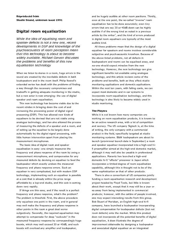
/
Reproduced from Studio Sound, unknown issue 1991speaker defects is not Reproduced from Studio Sound, unknown issue 1991speaker defects is not

Reproduced from Studio Sound, unknown issue 1991speaker defects is not - PDF document

myesha-ticknor
myesha-ticknor . @myesha-ticknor
Follow
376 views
Uploaded On 2016-06-02

Reproduced from Studio Sound, unknown issue 1991speaker defects is not - PPT Presentation

system In order that the reader not be misled the writer must declare an interest he has been employed as a consultant on the BW project although the main work was done by Peter Craven and Colin ID: 345397

system. order that the

Share:

Link:

Embed:

Download Presentation from below link

Download Pdf The PPT/PDF document "Reproduced from Studio Sound, unknown is..." is the property of its rightful owner. Permission is granted to download and print the materials on this web site for personal, non-commercial use only, and to display it on your personal computer provided you do not modify the materials and that you retain all copyright notices contained in the materials. By downloading content from our website, you accept the terms of this agreement.


Presentation Transcript

Reproduced from Studio Sound, unknown issue 1991speaker defects is not a new one, recent developments in DSP and knowledge of the psychoacoustics of room perception mean that this technology is about to become widely available. Michael Gerzon discusses the problems and benefits of this new equalisation technologyWhen we listen to stereo in a room, huge errors in the sound are created by the inevitable defects in both loudspeakers and in the room itself. Philip Newell’s extended series has dealt with the problems of finding a way through the necessary compromises and system. In order that the reader not be misled, the writer must declare an interest; he has been employed as a consultant on the B&W project, although the main work was done by Peter Craven and Colin Bean. However, I hope that my comments are not biased in favour of particular contenders. It remains to be seenequalisation contenders emerge from the woodwork either in Japan or from continental Europe. In particular, it is not known how close participants, notably KEF and Bang and Olufsen, in the Eureka Archimedes room response analysis project are to devising such products. What Can Be Equalised? Traditionally, loudspeakers and rooms have been equalised using graphic (or, more rarely, parametric) equalisers, but it is widely recognised that at best these can give only a limited improvement, and at worst can make the sound markedly worse. The problems of loudspeakers in rooms are not merely that the frequency response is not flat, but that there are time-domain problems with delayed reflections and reverberation. Graphic equalisers generally cannot tackle the time domain problems, and even the frequency response errors can only be corrected to a limited degree due to the one-third octave resolution of typical graphic equalisers, which is coarser than the critical-bandwidth resolution of the human ear. Empirical experience of equalising PA systems with parametric equalisers suggests that equalisers with a Q of about 10 are required to tame simple frequency response effects well subjectively. If one wishes that the speaker and room equalisation not introduce audible side effects that are worse than the original problems, one must ask what aspects of the sound should be equalised, and what should be left alone. This is the problem that all who have worked on room equalisation have had to tackle. There seems to be a broad consensus on the broad outlines of what should be done2,3, but the fine details still are the subject of research and possible controversy. Even after deciding what aspects of the sound to equalise, the fact is that the ideal equaliser required is still very complex and expensive (typically using of the order of 50,000 taps per channel), so that there is also the problem of how to approximate the ideally desired equaliser with cost-effective DSP technology likely to be affordable to the customer, and this also involves practical trade-offs that vary between different systems. We shall first look at two problems that affect what we can in practice equalise. One thing we want an equaliser to do is to flatnot at the expense of boosting dips or notches in the frequency response to the point where the boost causes amplifier and speaker overload or massive amounts of the boosted frequency at other listening positions. To overcome this problem, one needs to measure the original room frequency response, and not to equalise for the actual measured response, but for a “regularised” version of the room response which, in some manner, has filled in deep troughs of the measured response. It is a fortunate fact of life that the ears are known to be much less sensitive to the odd trough in a frequency response than to peaks of similar magnitude, so that equalising in a manner that leaves some of these troughs in the final overall response, while equalising out the peaks, gives a subjective improvement, while avoiding the problem of excessive boosts. Most workers in room equalisation recognise the necessity of not attempting to equalise fully the troughs or dips in the original frequency response. Digital room equalisation can, in principle at one room point, not only equalise the frequency response, but also correct time-domain problems such as reflections off walls and reverberation. The trouble is that this correction can only be done for one point and that the time domain response is made much worse elsewhere. So the problem arises of how much of the room’s time-domain problems can in practice be corrected, and how. Again agreement on what can and can’t be done, but there are some surprises which need a degree of detailed explanation. For those who understand the concept, we shall conclude in the following that the basic room equalisation needs to be of minimum phase type, although there are significant exceptions to this if the best possible results are to be obtained. Pre-responses and Minimum Phase One of the basic principles of science is the law of causality, that asserts that an effect cannot precede its cause. A causal filter is one in which the output does not emerge earlier than the input, and of course all real-world filters are of this type. In the digital domain, by adding an overall time delay so that one can have responses occurring before the input (although after the actual input), one can simulate the effect of an acausal filter ( one whose output responds before the input arrives), at the expense of having to wait a little. A filter is said to have an inverse filter if the result of cascading the filter with its inverse is to give back the original input signal, the inverse filter exactly compensates the effect of the original filter. A causal (real world) filter is said to be minimum phase if its inverse is also causal. The type of filters found in most graphic and parametric equalisers are minimum phase, but it is found that, except for almost anechoic rooms or very close to the sound source in normal rooms, the measured room response is almost never minimum . This means that any equaliser that attempts to compensate fully for the response of a room will be acausal, and will have a pre-response occurring before the arrival of the input. This in itself is not a serious problem with digital equalisers, as we can incorporate e equalisation that allows to occur. The real problem is that at points in the room other than that of the measurement microphone, this pre-response and the room response do not completely cancel each other out, so that one hears a “pre-echo” or pre-response before the main sound arrives. As noted in references 1 and 3, such pre-responses sound highly unnatural in general, and are very audible. Some writersclaim that not more than 2 msec of pre-response should be allowed, although in the B&W project, at least one important exception to this rule has been identified. While I shall deal with exceptions later, generally, room equalisation should be of minimum phase type to avoid problems with audible pre-responses when cancellation of the room response is imperfect. Minimum phase filters have a lot of special properties that arise from long-known deep mathematical results, and there are many ways of ensuring that a room equalisation filter is minimum phase. Many workers in room equalisation have derived minimum phase filters using what are termed LMS algorithms (Least Mean Square algorithms), based on work in the theory of linear prediction. Roughly speaking, such algorithms attempt, for a given complexity of filter, to minimise the error energy caused by the approximate inverse filter. While the theory of LMS filtering is widely available and understood, it is unfortunate, as noted in reference 1, that the ears do not seem to respond to the total power of the error in equalisation, but rather seem much more sensitive to some kinds of very low level errors (even those as much as 80dB down) than to other errors of a very such larger magnitude, which seem almost innocuous. Thus LMS algorithms, while they minimise an objective measure of the error in equalisation, do not minimise the subjective error, and in fact are found to be very poor indeed subjectively. For this reason, the B&W project has adopted an alternative approach to deriving minimum phase equalisation filters that incorporates subjective criteria. One of the remarkable things about minimum phase filters is that the overall frequency and phase response of the filter can be computed, by a mathematical method involving the Hilbert transform, just from a knowledge of the amplitude frequency response alone. In other words, if one knows what frequency response one wishes to correct, the phase response aspects of the filter follow automatically. This has the very convenient side-effect that one can devise the equaliser by computations in the frequency domain rather than in the time domain. This allows one to regularise the measured room frequency response to eliminate dips in the response, and also to smooth the measured frequency response at higher frequencies, where it is found that one does not wish to equalise too fine detail in the frequency response (since this varies from point to point in the room). While the third-octave equalisation of conventional graphic equalisers is too coarse, Sigtech have found that equalisation to one-eighth of an octave resolution works well in their system at higher frequencies. Another advantage of being able to derive minimum phase equalisers just from a measurement of the amplitude of the frequency response is that one can measure the spectral power (frequency) response at several points across a listening area, and equalise for averaged frequency response at all these points, rather than for the frequency response measured at just one point. This gives better results across the whole listening area, at the expense of less good results very near one single point. It has been found in practice that, under domestic conditions, averaging for six points across, say a settee, can give useful room equalisation across the listening area. Sigtech’s studio system, on the other hand, uses a single measuring point, and is designed to equalise the optimum monitoring position in a studio situation. One advantage of averaging the measured response at several room points is that this tends to “fill in” measured dips in the frequency response. Nevertheless, it is found that regularisation of the troughs is still necessary to avoid excessive boosts, since by no means all troughs are adequately filled in by averaging over just six points. Time Domain Effects By using minimum phase equalisation, which depends only on the measured amplitude frequency response, and not on the measured phase response, one appears to have thrown away any possibility of compensating for time-domain effects in the room. One of the surprises revealed by B&W’s researches was that minimum phase equalisation can significantly improve the time-domain performance of a room as well. This is an interesting phenomenon that is not completely understood. It appears that the fine detail in the frequency response, especially at frequencies below 300 or 500Hz, contains a great deal of hidden information about a room’s time domain response. Conventional minimum phase equalisers, such as graphic or parametric equalisers, ignore this fine detail so do not have much effect on time domain behaviour, but a minimum phase equaliser compensating for fine details of frequency response appears to cancel out about half of the unwanted time domain information. In particular, minimum phase equalisation approximately halves room reverberation time at low frequencies near the measurement positions – a very useful improvement at those lower frequencies that are most difficult to control by standard acoustic treatments. This improvement in reverberation time behaviour only occurs if the length of the response of the equaliser filter is significantly longer than the reverberation time of the room; the B&W filter has, at low frequencies, a total length of about 1 second, so as to cope with most domestic rooms, whereas the Sigtech filter only has a length of about 100msec, and so is unable to respond long enough to improve the reverberation time. This observation brings us to the problems of implementation of room equalisers, since the reason why Sigtech’s processor has such a short filter is to do with the limitations of affordable DSP technology. DSP Complexity The ideal equaliser for a room would use a filter with about 50,000 taps per channel, but such filters are extremely expensive at present, although costs are falling fairly rapidly. Because of the high costs, Sigtech’s current filters use a more affordable 2200 taps, which is enough to do a useful LMS equalisation of at least a monitor room acoustic, but not enough to control effects more than 40dB below the wanted signal, such as the decay tail of reverberation in a domestic room. The B&W approach has reduced processor complexity by observing that it is only at low frequencies below about 500Hz that one requires a long filter length, and that the reduced frequency resolution needed at high frequencies means that a much shorter filter length can be used for the higher frequency equalisation. By using a process well known to communication engineers called decimation, the signal is first split into two or three frequency bands, one below 500Hz, one between 500Hz and for example 3kHz, and one above 3kHz, and each frequency range is represented at a different sampling rate. For example (and these figures are illustrative and not necessarily those used in the forthcoming commercial product), if the input is sampled at 48kHz, so is the band above 3kHz, whereas the band between 500Hz and 3kHz would be sampled at just 6kHz sampling rate, and the band up to 500Hz at a 1kHz sampling rate. At a 1kHz sampling rate, one only needs one forty-eighth of the memory to store information for a filter of a given length as compared to what one needs at 48kHz, and also, one has to do computation only one forty-eighth as often, since the samples occur that much less often in time. This means that one only needs to do 1/(48), which equals about 1/2300, of the amount off computation that is required at 48kHz sampling rate for a given filter length below 500Hz. A significant saving is also made (by a factor 64) for the shorter filters required in the mid-frequency band, and only in the highest frequency band, where the full sampling rate is used, is no saving obtained. However, in this highest band, only very short filters are required for equalisation purposes, so that great processing power in the DSP chip is not required. The use of decimation to reduce the processing requirements to fit available DSP chips is a key to both the relatively low cost of the B&W processor and its very long filter length. The price paid for this cost saving is a considerable increase in the development effort required to get such a complicated signal processing algorithm to work. There are many difficult problems in getting high-quality decimation algorithm to work well, and it is doubtful that the B&W system would have been possible without the use of some very powerful software toolwho is almost unique in combining such advanced software skills with a detailed knowledge of the subtleties involved in high-quality audio. Room Measurement The measurement of the room response is not a trivial operation, and considerable work has been done on attempting to do this well. In principle one could simply feed the loudspeaker with a sharp impulse, and measure the impulse response at the microphone, and then use standard well-known mathematical methods to derive from the impulse response the room response. The problem with this is the fact that the power in an impulse that can be fed to a speaker and amplifier without overloading them is limited, and any room noise will degrade measurement accuracy rather badly. Even in a really “quiet” control room, the amount of low frequency noise due both to air conditioning and, surprisingly, to natural variations in atmospheric pressure due to high-frequency components of the weather, is enough to make impulse measurements totally useless. The situation in domestic rooms, where noise levels are often much higher, is even worse. For this reason, all workers in this area use test signals that have much higher power than an impulse, usually either a pseudo-random test sequence or a chirp test signal. By a process known as deconvolution, it is possible to derive an impulse response from the output of the measurement microphone when such a sequence or chirp is fed to the speaker. Such test signals often last one or several seconds in duration, and have many thousands of times as much power as a single impulse, and give a correspondingly improved signal-to-noise ratio in the measurement. Even so, averaging over a number of measurements is required to minimise noise errors. Another problem in making the measurement is that if too high a level of test signal is fed to the speakers, they will produce distortion which will cause significant errors in the measurement. Especially in the B&W case, where errors 80dB down can affect the reverberation time of the equalised room, it has been found important to use measurement procedures that minimise the effect of nonlinear speaker distortions. Even after all these precautions are taken, noise problems remain severe at the lowest frequencies, w about 50Hz, and sophisticated methods are required in deriving the room equalisation to minimise the effects of room equalisation. Equalisation of the low frequency behaviour of both the room and the loudspeaker is important subjectively, and cannot be done well unless a very long filter length of the order of a second is used – another reason why the B&W system uses decimation in order to achieve the required low-frequency resolution and filter length. Bass Response The problem of bass response is particular important digital equalisation. All loudspeakers have a roll-off in the extreme bass, almost always of a minimum phase type. Minimum-phase bass roll-offs produce very severe phase distortions, not only near the roll-off frequency, but several octaves higher, and these phase distortions cause a “woolly” quality that hitherto has been unavoidable. The only way in the past to reduce these phase distortions has been to lower the frequency at which the roll-off starts, but even lowering the roll-off to 5Hz, which is difficult, is not enough to eliminate audible phase distortion. Any attempt to lower the low frequency roll-off by minimum phase equalisation requires enormous ich can soon result in speaker or amplifier overload. While the digital signal processing algorithm can be designed to incorporate a limiter to prevent speaker or amplifier damage, such a limiter results in a loss of sound accuracy at high levels. While it is not practically possible to compensate the low-pass phase distortion by analogue filters (such filters would use several thousand precision analogue components!), it is possible to design in the digital domain a phase-equalisation all-pass filter, which does not effect the low-frequency amplitude response, but which does eliminate the phase response problems caused by the low-frequency roll-off. The actual length of such phase-compensation filters is a substantial fraction of a second, and so would be very expensive to implement as an FIR filter at full sampling rate, but such a filter is quite economical to implement at a lower decimated sampling rate. Since the very low-frequency performance of a speaker in a room is very difficult to measure, even in most anechoic chambers, the phase compensation is derived from the theoretical bass alignment of the loudspeaker, possibly supplemented by near-field measurements. Adjustments can be provided for standard speaker bass alignments on the control unit, with preset settings for particular models of loudspeakers. The subjective effect of phase compensation of the bass from loudspeakers is very marked, giving a much tighter and more “punchy” quality, with greater transparency, and interestingly a subjective extension of bass response of a least half an octave. The improvement is audible even on loudspeakers with a very high cut-off frequency, such as Quad electrostatic designs. The bass phase compensation, which as already remarked has a significant effect even in midrange frequencies, is a very non-minimum phase filter, and has very substantial pre-response. Despite this, it is found not to be subjectively disturbing in the way that spurious room pre-responses are. The benefits of bass phase equalisation are considered, by those who have heard it, to be a substantial improvement over whatwas hitherto possible with analogue technology, and digital equalisation provides a way of improving bass performance without going to ridiculously large giant space-consuming power-hungry monster speakers, and is certainly a much cheaper route. Cross-Over Compensation While the room requires minimum phase equalisation to avoid pre-response effects, phase anomalies in loudspeaker systems can respond well to digital non-minimum phase compensation. Besides the poor phase response caused by bass roll-offs, the other main cause of phase distortion in loudspeakers is the cross-over networks. With analogue circuitry, it is impossible to design a crossover network that has both an adequately rapid cross-over rate and a flat phase response. Again, experiments have shown compensating for the phase response anomalies of the crossover networks, while ignoring any phase response anomalies at the same frequencies of the room, gives a marked improvement in subjective quality. The all-pass behaviour of cross-over networks is not minimum phase, so that the compensating all-pass filter is a pre-response. Such digital equalisation of non-minimum phase speaker phase anomalies is subjectively important, and is another exception to the earlier rule that speaker/room equalisation should be minimum phase. Many high-rate crossover networks have a Q higher then 0.6, which causes audible colouration. Correction of this colouration by digital equalisation gives a much cleaner sound even on recordings, such as UHJ encoded material, that have passed through low-Q all-pass phase distortion networks. In general, equalisation of known sources of phase distortion has proved to be subjectively much more beneficial than attempts to flatten the amplitude response of loudspeakers. It is quite easy, using digital equalisation, to obtain a ruler-flat textbook perfect frequency response from a loudspeaker, but in general this will not sound any better (and may sound considerably worse) than the unequalised speaker. When digital equalisation comes into widespread use, be extremely suspicious of loudspeakers incorporating digital equalisers that have a measured ruler flat on-axis anechoic response; such a measurement may please the advertising boys, but is likely to be at the expense of more important speaker characteristics! Combining Room and Speaker EQ Given that the requirements of equalising the speaker and the room are so different, there is the problem of separating the effects of the speaker and the room when measuring the room. Naively, one sight think that all one has to do in measuring the room is to send a test signal through an equaliser for the speaker before sending it to the speaker and room and that the result picked up by the microphone will be the room response. Unfortunately, it is not quite that simple, partly because one has compensated the low frequency phase portion of the speaker response, but not its amplitude, and any attempts to compensate for the amplitude error in the minimum phase room equaliser will also add additional unwanted compensatory phase distortion. The method of measuring the room component of the equalisation requires careful modelling of the speaker equalisation within the measurement algorithm, and involved quite a lot of thought in the B&W development program. The additional problem of excessive measurement noise at low frequencies requires careful design of the equalisation algorithm based on in-room measurements, so that the benefits of speaker bass equalisation are retained and so that room bass resonance effects are controlled without spurious noise artefacts. In the B&W system, it has been found that attempts to equalise the loudspeaker and the room as a single system by overall minimum phase equalisation do not give optimum results, and that quite a sophisticated separation of these two components is required, with quite a complicated joint equalisation strategy. There appear to be significant psychoacoustic differences between equalisation errors generated over a small volume such as that of a loudspeaker and those generated over a large volume such as a room. There is still a lot to be learned about the precise dividing line between loudspeaker and room effects. Providing a good average equalisation over a chosen listening area does not guarantee that results will always be good. For example, variations in air temperature and humidity change the room response, and one might fear that the room equalisation will no longer work. Such fears have proved largely unfounded, as have fears that the effect of moving a small item of equipment or another person coming into the room might be to wreck the effect of room equalisation. While obviously, it is best to determine the room equalisation under the actual conditions of listening, it is found that the results are fairly tolerant of typical small changes over the useable listening This tolerance to normal small changes in room acoustics arises largely because the equaliser does not attempt to correct fine details of the room response at higher frequencies, which are most subject to change. Careful room equalisation will give significant improvements over the listening area it is designed to serve, which in domestic use may be around 2 metres wide, but in practice it is also important that the equalisation should not significantly degrade results away from this optimum listening area. It has been found in the B&W program that well-behaved equalisation algorithms can still give improvements away from the optimum listening area, partly due to the improvements given by speaker phase equalisation, and partly due to the equaliser “sucking out” obtrusive low frequency room resonances. It is obvious that room/speaker equalisation cannot turn a sow’s ear into a silk purse, and the benefits of such equalisation are best appreciated with systems that are already basically good. There is no excuse for bad speaker or control room design. Rather, digital equalisation will help make already good systems a little more consistent and will reduce system-dependent colourations. History It is significant that the two companies, B&W and Sigtech, who are launching speaker/room equaliser products first both involve people who were involved with early pioneering investigations into sophisticated equaliser algorithms. Peter Fryer, the technical director or B&W, published the first detailed work on using FIR filters for speaker and room equalisation as long ago as 1980. At that time working for Wharfedale, he described the use of analogue charge-coupled FIR filters aligned to compensate for measured room and speaker responses. Ronald Genereux, a Vice-President of Sigtech, was a participant in the earliest commercial digital FIR filter room/speaker response equalisation project at AR in the early 1980s, a project that was handicapped by the inadequate DSP technology of the The involvement of people with around a decade of prior experience in equalisation algorithms for rooms and speakers is indicative of the degree to which empirical experience of the problems is a necessary prerequisite to designing subjectively acceptable equalisers. This is not an area where mere engineering skills are adequate. While high-level engineering skills are certainly necessary, other subjective skills are vital. Although the processing in the equalisers takes place in the digital domain, it is necessary to convert the results into the analogue domain to feed the amplifiers and speakers. The quality requirements for the D/A converters are particularly stringent in this application, and far more severe than for the D/A converters in CD players or digital tape machines. This is because the material on CD or tape is generally of a restricted dynamic range, say the 92dB of 16 bit digital audio. However, the output of the digital equaliser may well have been subjected to digital gain control to turn the level up or down, and will also have been subjected to frequency-dependent boosts and cuts which will cause the output signal to have a far wider dynamic range than the input source signal. For this reason, even when the input is conventional 16 bit source material, the output D/A converters must work well over a far wider dynamic range, and 20 bit performance is desirable and it would be useful to have converters that exceed this, especially in terms of linearity, where even a 24 bit performance would not come amiss. Since all source material, whether it originated from CD, analoguel tape, live microphones, or off-air broadcasts, is being passed through these final D/A converters, it is desirable that these converters should perform better than the quality of any material being thrown at them. Thus it is not surprising that companies that are developing digitally equalised speaker products, such as Meridian or B&W, take the problem of getting the best possible performance out of D/A converters particularly seriously. It is a paradox that loudspeaker companies, whose skills are traditionally the furthest from those of hi-tech digital technology, should actually be those companies who are pushing the high-quality aspects of digital conversion and processing the hardest. This is precisely because their applications are the most stringent as regards quality. While having done little on room equalisation, the case of Bob Stuart at Meridian is particularly interesting. Rather than develop a digital equaliser for an analogue speaker system, he has developed a speaker where the crossover design was also implemented using digital equalisers. In other words, the speaker design, from the beginning, is conceived in terms of digital signal processing. Such an integrated digital speaker design permits the crossover performance to be optimised for the speaker units without any of the compromises forced by the use of analogue crossover networks, whether passive or active. In particular, not only is it possible to ensure on-axis phase linearity (something that overall digital equalisation of a speaker system can give), but the crossover rates and the off-axis phase performance can also be optimised. Stuart also has the reputation of designing some of the best D/A and A/D converter systems around, based on commercial chip-sets, but skilfully optimised in subjective and objective performance. This kind of integration of historically disparate skills will be increasingly important as technologies like digital room/speaker equalisation become more important. Equaliser types Most attempts at sophisticated digital room/speaker equalisation have been based on FIR (finite impulse response) filters, tapped delay line or transversal filters, since the theory of designing such equalisers is well understood. However, it is also possible to design speaker and room equalisers using recursive filters (filters with feedback paths), for example as described by Greenfield and Hawksford. In general, recursive filtering might be expected to suffer less from undesirable effects due to limited filter complexity, but it is not obvious which of recursive or FIR types of filters is best in room/speaker equalisation applications. The Sigtech product is based on FIR filters, whereas in some situations, a combination of FIR and recursive filters, or an equaliser based on recursive filters, might be used in other products. Among other unknowns at present is the optimum kind of microphone that should be used for room response measurements; both Sigtech and B&W use an omnidirectional microphone, and certainly omnidirectional types are the most accurate for measurement purposes. However, there may be advantages in using directional types, cardioids, for measurements so as to discriminate which part of a room’s acoustic is being equalised. This and many other areas are still the subject of further research. Both Sigtech’s and B&W’s products are based on separate monophonic equalisation of each of the speakers in a stereo pair, and some kind of stereo matrix equaliser, cross-feeding the two channels between the loudspeakers, may give improved results at a single listening position. However, there is no evidence that stereo matrix room equalisation offers any advantage over extended listening areas. However, once one has multiple loudspeakers dotted around the room, as in home cinema or HDTV applications, the additional loudspeakers provide the possibility of controlling low frequency room colouration by using the principles of “active absorption”, where the room response is used to provide electronically assisted absorption by the speakers of room resonances. However, active absorption techniques are not used in the first generation of room/speaker equalisation products, and in practice are unlikely to be applicable to use with just two loudspeakers, since these do not give adequate absorption of resonances. Conclusions The whole area of digital room/speaker equalisation is an exciting development that will permit some of the traditional problems of analogue speaker technology, such as phase response anomalies, especially in the bass, to be solved, and will allow a degree of control of low frequency room resonances and reverberation across a useful listening area. While room equalisation cannot perform miracles, it is another step towards getting more accurate and repeatable results. The improvements obtained are generally not spectacular, but give a less muddled and more accurate sound, important for high quality domestic and monitoring applications. It is a difficult technology to master, relying on a considerable amount of psychoacoustic knowhow and experience, just like the traditional arts of speaker and room acoustic design. Digital equalisation provides another very useful tool complementing these more traditional skills, capable of giving better overall results than was hitherto possible using just analogue technology. References 1) Michael Gerzon, “Why Do Equalisers Sound Different?”, Studio Sound, vol 32, no 7, pp58-65 (July 1990) 2) C Bean and P Craven, “Loudspeaker and Room Correction Using Digital Signal Processing”, Preprint 2756, 86th Audio Engineering Society Convention, Hamburg, 1989 March 3) Ronald P Genereux, “Adaptive Loudspeaker Systems: Correcting for the Acoustic Environment”, Proc 8th International Audio Engineering Society Conference, Washington DC, May 1990 4) S T Neely and J B Allen, “Invertibility of a Room Impulse Response”, Journal of the Acoustical Society of America, vol 68, pp165-9 (July 1979) 5) Phillip Newell, “ Monitor Systems Part Five: Crossovers”, Studio Sound, vol 31, no 12, pp 60-67 (December 1989) and Part Six, Studio Sound, vol 32, no 1, pp48-53 (January 1990) 6) P A Fryer S R Lee, “Use of Tapped Delay Lines in Speaker Work”, Preprint 1588, 65th Audio Engineering Society Convention, London, 25-28 February 1980 7) R G Greenfield and M O J Hawksford, “A Comparative Study of FIR and IIR Digital Equalization Techniques For Loudspeaker Systems”, Proceedings of the Institute of Acoustics, vol 12, part 8, pp77-86 (November 1990) The Gerzon Archive www.audiosignal.co.uk