/
CT scan  By  S.S.Siva   Sagar CT scan  By  S.S.Siva   Sagar

CT scan By S.S.Siva Sagar - PowerPoint Presentation

naomi
naomi . @naomi
Follow
64 views
Uploaded On 2024-01-29

CT scan By S.S.Siva Sagar - PPT Presentation

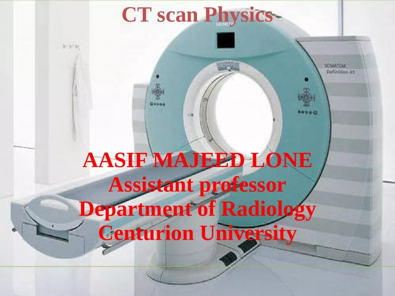
10 MSc RIT 200513001 SGT UNIVERSITY CT scan Physics AASIF MAJEED LONE Assistant professor Department of Radiology Centurion University Introduction At the annual Congress of British institute of radiology ID: 1041894

ray image detector patient image ray patient detector tube detectors beam artifacts scan scanner attenuation generation gantry high images

Share:

Link:

Embed:

Download Presentation from below link

Download Presentation The PPT/PDF document "CT scan By S.S.Siva Sagar" is the property of its rightful owner. Permission is granted to download and print the materials on this web site for personal, non-commercial use only, and to display it on your personal computer provided you do not modify the materials and that you retain all copyright notices contained in the materials. By downloading content from our website, you accept the terms of this agreement.


Presentation Transcript

1. CT scan By S.S.Siva Sagar M.Sc RIT200513001SGT UNIVERSITYCT scan PhysicsAASIF MAJEED LONEAssistant professorDepartment of RadiologyCenturion University

2. IntroductionAt the annual Congress of British institute of radiology , in April of 1972 , Godfrey Newbold Hounsfield, a senior research scientist At EMI limited (Electric and Musical Industries), middlesex, England , announced the revolutionary imaging technique called computerized axial Transverse Scanning. He considered as a Father of Ct scan.Allan MacLeod Cormack developed the mathematics used to reconstruct the images in 1963.Noble prize was given to the discovery in 1979, for both GN hounsfield (UK) and Alan coremack (USA). Perhaps the first significant technical development came in 1974 when Dr. Robert Ledley, a professor of radiology, physiology, and biophysics at Georgetown University, developed the first whole-body CT scanner. (Hounsfield’s EMI scanner scanned only the head.)

3. In 1989, Dr. Willi Kalender has made significant contributions to the introduction and development of volume spiral CT scanning.

4. Terminology Translation is the linear movement of X ray tube and detector.Rotation is the rotatory movement of X ray tube and detector.Ray refers single transmission measurement.Projection refers series of X rays passes through the patient at the same orientation.

5.

6. Pitch = table movement per axial scan(table feed) / slice thickness.If pitch increases Radiation dose, Image quality and Scanning time decreases.If increment increases No of images decreases and If increment decreases no of images increases. CT number or hounsfield unit :

7. SUBSTANCEHUAir-1000Lung-500Fat-100 to -50Water0CSF15Kidney30Blood+30 to +45Muscle+10 to +40Grey matter+37 to +45White matter+20 to +30Liver+40 to +60Soft tissue+100 to +300Bone1000

8. In CT, a high-kilovolt technique (about 120 kV) is generally used for the following reasons:1. To reduce the dependence of attenuation coefficients on photon energy.2. To reduce the contrast of bone relative to soft tissues.3. To produce a high radiation flux at the detector.

9. Basic principle Of CTThe fundamental concept is the internal structure of an object can be reconstructed from multiple projections of the object.Computerized tomography means A method Of producing three dimensional images Of internal body structure by two dimensional images (axial images)The Ray projections are formed by scanning a thin cross section of the body with a narrow x ray beam and measuring the transmitted radiation with a sensitive radiation detector.The detector does not form the image.It adds up the energy of all the transmitted photons.The numerical data ray sums are then computer processed to reconstruct an image.Human body is imagined as a matrix and is divided into number of columns and rows.In general, CT scanners used 512 x 512 and 1024 x 1024 columns and rows. Each matrix element is named as picture element ( pixel) in a 2- dimensional concept.

10. Pixel size is 0.625 mm, Detector size – 0.625 mm and minimal slice thickness called pixel size.Volume element (voxel) represents a volume of tissue in the patient and it is three dimensional concept.Voxels are scanned in different directions. Each pixel on the monitor display represents a voxel in the patient.When the voxel dimensions of length, width, and height are equal, that is, describe a perfect cube, the imaging process is referred to as Isotropic imaging.Finally, each pixel in the CT image can have a range of gray shades. The image can have 256 (2⁸), 512 (2⁹), 1024 (2 10), or 2048 (2 11) different grayscale values. Because these numbers are represented as bits, a CT image can be characterized by the number of bits per pixel. CT images can have 8, 9, 10, 11, or 12 bits per pixel. The image therefore consists of a series of bit planes referred to the bit depth.

11.

12.

13.

14. Windowing :The CT image is composed of a range of CT numbers (e.g., +1000 to 1000, for a total of 2000 numbers) that represent varying shades of gray.The range of CT numbers is referred to as the window width (WW), and it controls the contrast.The center of the range is the window level (WL) or window center (C), and it controls image brightness. Both the WW and WL are located on the control console. With a WW of 2000 and a WL of 0, the entire gray scale is displayed and the ability of the observer to perceive small differences in soft tissue attenuation will be lost because the human eye can perceive only about 40 shades of gray.The WL or C increases the image goes from white (bright) to dark (less bright); and the image contrast changes for different values of WWs. The image contrast is optimized for the anatomy under study, and therefore specified values of WW and WL or C must be used during the initial scanning of the patient.

15.

16. Why Is a CT Scan Performed ?A CT scan has many uses, but it’s particularly well-suited for diagnosing diseases and evaluating injuries. The imaging technique can help your doctor:-Diagnose infections, muscle disorders, and bone fracturesPinpoint the location of masses and tumors (including cancer)Study of the blood vessels and other internal structures.Assess the extent of internal injuries and internal bleeding.Guide procedures, such as surgeries and biopsiesMonitor the effectiveness of treatments for certain medical conditions, including cancer and heart disease. etc.

17. AdvantagesIt is minimal invasive procedure.Relatively inexpensive compared with MRI , PET and SPECT scanning.Rapid acquisition of data and no need for patients to remain for planning process.Better resolution .Minimum time taking procedure compared with MRI, PET etc.To overcome superimposition of structures. To improve contrast of the image. To measure small differences in tissue contrast.

18. The special features of CT image includesImages are crosssectional.Eliminates the superimposition of structures.Sensitivity of CT to subtle difference in x ray attenuation is at least factor 10 higher than x ray film.Higher contrast due to elimination of scatter

19.

20. TUBE WARM UP PROCEDUREThe purpose of an X-ray tube’s warm-up procedure is to avoid damage to the X-ray tube and avoid any artifacts in the images acquired. If a cold anode is exposed to high-powered energy, anode damage often occurs. A general recommendation is proposed by all manufacturers for warming of the X-ray tubes by different series of low energy exposures to prevent such type of damage.The X-ray tube’s heating procedure is performed by carefully increasing the tube current and voltage, leading to the slow burning of any oxygen molecules present before reaching a safe level for high-powered operation of the tube.The tube is warmed up gradually in a controlled manner, so the tube can reach its operating temperature before scanning a patient.

21. The CT manufacturers have recommended in the respective CT manuals. Never to perform scanner calibration, scanner testing, or tube heating when a patient or other personnel are present in the CT room.The system operates most efficiently within certain parameters. These parameters are established by warming the tube using a preset group of exposures. When you perform a tube warmup at least once every 24 hours and at any system prompt, it reduces the possibility of image artifacts, and may aid in prolonging the life of the tube.When you start the scan, a series of air scans are performed as part of the tube warm up scans.

22. HOW CT SCANNERS WORKTo enhance understanding of the early experiments and current technology, the technologist must be familiar with the way a CT scanner works.The technologist first turns on the scanner’s power and performs a quick test to ensure that the scanner is in good working order.The patient is in place in the scanner opening, with appropriate positioning for the particular examination. The technologist sets up the technical factors at the control console. Scanning can now begin.When X rays pass through the patient, they are attenuated and subsequently measured by the detectors. The x-ray tube and detectors are inside the gantry of the scanner and rotate around the patient during scanning. The detectors convert the x-ray photons (attenuation data) into electrical signals, or analog signals, which in turn must be converted into digital (numerical) data for input into the computer.

23. The computer then performs the image reconstruction process. The reconstructed image is in numerical form and must be converted into electrical signals for the technologist to view on a television monitor.The images and related data are then sent to the PACS, where a radiologist will be able to retrieve and interpret them. Finally, the image can be stored on magnetic tapes or optical disks

24. System components in ctCT scan contains following components.Control console.Computer.Couch .Gantry.

25. Control consoleThere are 3 consoles in ct, one for the technologist to operate the imaging system, one for the technologist to post process images and the other for the physician to view images.Ex : GE CT scan.The operating console is provided with meters , controls for selection of technique factors , movement of Gantry and table couch, image reconstruction commands, selection of kvp and mAs and slice thickness.The Radiologist in control console is used to see the images and write reports. In some institutions, work station provided for reporting of patient scans.

26. ComputerThe computer is used to solve more than 2,50,000 equations with the help of microprocessor. The computer system performs image manipulation and various image processing operations such as windowing, image enhancement, image enlargement and measurements, multiplanar reconstruction, three-dimensional (3D) imaging, an quantitative measurements.The computer system generally includes input output devices, central processing units, array processors, interface devices, back-projector processors, storage devices, and communications hardware. The computer system also includes software that allows each hardware component to perform specific tasks.The software includes plot of CT numbers, mean and standard deviation of CT values, ROI subtraction techniques , reconstruction of images in coronal, saggital and oblique.

27. CouchThe couch supports the patient comfortably and it is made up of low Z material like carbon fiber material.It has a motor for smooth patient Positioning.It moves longitudinally through Gantry aperture , indexed automatically and the table top can be removable. The vertical movement should provide a range of heights to make it easy for patients to mount and dismount the table This feature is especially useful in the examination of geriatric, trauma, and pediatric patients. Horizontal or longitudinal couch movements should enable the patient to be scanned from head to thighs without repositioning.Industry standard table weight limits for CT is usually 450 Ibs (205 kg). Newer larger CT scanners are currently available which can accommodate patients weighing up to 680 Ibs (308.4 kg).

28. Gantry The gantry is a mounted framework that surrounds the patient in a vertical plane. It contains a rotating scan frame onto which the x-ray generator, X ray tube, and other components are mounted.The generator in the gantry is usually a small, solid-state, high-frequency generator mounted on the rotating scan frames.The gantry houses imaging components such as the slip rings, x-ray tube, high-voltage generator, collimators, detectors, and the data acquisition system.Because it is located close to the X-ray tube, only a short high-tension cable is required to couple the x-ray tube and generator. This design eliminates external x-ray control cabinets and long high-tension cables as was typical of the older CT imaging systems.

29. Gantry cooling is a prime consideration because the ambient air temperature affects several components. In the past, air conditioners were placed in the gantry. Modern cooling systems circulate ambient air from the scanner room throughout the gantry.Most scanners have a 70-cm aperture that facilitates patient positioning and helps provide access to patients in emergency situations.The gantry also includes a set of laser beams to aid patient positioning.Other gantry characteristics include Scan control panels - controls gantry tilt and patient table elevationScan control box - controls emergency stop, intercom, and scan enable and pause functionsSlice position indicatorRadiation indicator, and Intercom systems with multilingual autovoice to facilitate communication with the patient in one of several languages.

30. CT Gantry has the following gadgets.X-ray tube.Collimators.Filters .Detectors.High voltage generator.

31. X ray tubeIdeally , the radiation source for CT should supply a monochromatic x ray beam. With monochromatic x ray beam image reconstruction is simpler and more accurate.Kvp : 80 to 140 kvp – Usually operated at 120kVmA : 50 to 1000 mA.Tubes are operated for prolonged exposure time at high mA.There are two focal spot sizes . Hrct uses small focal spot sizeHigh speed rotors in tubes for best heat dissipation.The Multislice CT tube is large in size; anode disc is larger in diameter and thickness. The anode heat capacity 8 MHU and the anode cooling is about 1 to 2 MHU.

32. CollimatorsCollimation in CT serves to ensure good image quality and to reduce unnecessary radiation doses for the patient. Collimators are present 1. Between the X - ray source and the patient (tube or pre - patient collimators) .2. Between the patient and the detectors (detector or post - patient collimators). The tube collimator is used to shape the X - ray fan beam before it penetrates the patient.it consists of a set of collimator blades made of highly absorbing materials such as tungsten or molybdenum. The opening of these blades is adjusted according to the selected slice width and the size and position of the focal spot.

33. FilterationThe X - ray photons emitted by the X - ray tube exhibit a wide spectrum. The soft, low - energy X - rays, which contribute strongly to the patient dose and scatter radiation but less to the detected signal should be removed. To achieve this goal, most CT manufacturers use X - ray filters.The Inherent filtration of the X-ray tube, typically 3 mm aluminum equivalent thickness, is the first filter. In addition, flat shaped filters can be used. Flat filters, made of copper or aluminum, are placed between the X - ray source and the patient. They modify the X - ray spectrum uniformly across the entire field of view.

34. The cross - section of a patient is mostly oval - shaped, so Bowtie filters have an increased thickness from center to periphery, allowing them to attenuate radiation hardly at all in the center but strongly in the periphery. They are made from a material with a low atomic number and high density, such as Teflon.

35. High voltage generatorIt is mounted on the Gantry which takes 0.3 secs for 360 degrees rotation.The generator is a high frequency generator with the capacity of 60 KWIt provides stable tube current and voltage is controlled by microprocessor.The generator can give a tube current of about 800 mA and 125 KV with pulse duration of 2 to 4 Milliseconds.

36. Detectors The requirements of CT scan detector are as follows –Small in size with good resolutionHigh detection efficiencyFast Response and Negligible after glow.Wide dynamic rangeDecrease the Noise.There are two types of detectors used in ct scanners. These areScintillation detectors used in Multi Slice scannersXenon gas ionization Chambers used in Single Slice Scanners

37. Scintillation detectorsScintillation crystals are extremely large number of materials that produce light as a result of some external influence.When ionizing radiation reacts with scintillation crystals that produce light (scintillate).The number of light photons proportional to the energy of incident x ray photon.This is just what intensifying screen does.Some of these light photons will be emitted promptly and produce the desired signal.

38. Some light photons will be delayed and produce produce afterglow.This process done by photomultiplier tubes. The first two generations used thallium - activated sodium iodide scintillation crystals attached to photomultiplier tubes.Sodium iodide crystals have some disadvantages. They arePM tubes are big and not easily fit into the large array of detectors .NaI is hydroscopic and requires air tight container and it has a long afterglow.

39.

40. There are several possibilities for replacing nai. These include cesium iodide , bismuth germinate and cadmium tungstate.Photomultiplier tubes have been replaced with silicon photodiodes . A photo diode convert a light signal into an electric current or signal..Photo diodes offer the advantage of smaller size, greater stability and lower cost.

41.

42. Xenon gas ionization Chambers Any gas filled detector contains An anode and cathode.A counting gas ( inert gas ).A voltage between the anode and cathode.Walls that separate the detector from the rest of the world.A window for the radiation photon to enter the detector.

43.

44. The photon enters into detector through a window.The photon intercts with a gas atom by ionizing the atom into electron pair.The voltage between the anode and cathode will cause the electron to move toward the anode and the positive ion move towards the cathode. When the electrons reach the anode , they produce small current in the anode. This small current is the output signal from the detector.

45. Gas filled detectors may operate in one of three modes.For low voltage, only the negative ions produced by the photon are collected by the anode. A gas filled detector operating in this mode is called ionization chamber. The important characteristicis that the current is directly proportional to the intensity of the incoming radiation.At the voltage increases, the ions moving under the influence of the voltage acquire sufficient energy to produce secondary ionization of the gas atoms. In this mode gas filled detector is called proportional counter. It's main characterstic is that output signal is proportional to the energy of photon.

46. With high voltage , the secondary ionization is so large that the energy proportionally is lost and all incoming photons register the same size pulse. In this mode, the gas filled detector is called Geiger Muller counter. It's main characterstic is large signals that are easily recorded.Hand carried survey meters are this type of detector.The disadvantage of xenon gas detector is a reduced efficacy . The overall detection efficacy is approximately 50 %.

47. The efficacy can improved by three waysBy using xenon , the heaviest of the inert gases. ( Z=54)By compressing the xenon 8 to 10 atmospheric pressure to increase it's density.By increasing the length of the chamber to increase the number of atoms along the path of x ray beam.

48. ADVANCEMENTS

49. 1) GEMSTONE DETECTOR (GE)100 times faster than GOS(0.03µs)245mm/s scan speed Isotropic ceramic with a highly uniform and translucent cubic structure.Faster light emission and shorter after-glowClarity DAS enables 25% reduction in electronic noise The Gemstone scintillator escalates response to X-ray excitation, reportedly 50 to 100 times faster than any other detector on the market. The higher speed improves temporal and spatial resolution and reduces electronic noise.This is mostly used in Dual Source or Dual energy CT Scanner.

50. DETECTORNEW INTEGRATED MODULE

51. 2) Nano-Panel Prism Detector (PHILPS)Consists of 3 main components Scintillators -Top-layer Yttrium-based garnet scintillator for detection of lower energies. Bottom-layer Gadolinium oxysulphide (GOS) scintillator for detection of higher energiesThin front-illuminated photodiode (FIP)-maintains overall geometric efficiency of the detectorApplication Specific Integrated Circuit (ASIC) –for analog-to-digital conversion

52. 3D Tile Patterned Arrangement

53. ADVANTAGESWide dynamic range and low noise.Minimum slice thickness of 0.625 mmSupports rotation time as fast as 0.27s.The FIP usage allow 25% higher light output and 30% less cross talk than previous detectors.Delivers color quantification and the ability to characterize structure based on material content

54.

55. 3) STELLAR DETECTOR(SIEMENS) Siemens Healthineers’ first fully integrated detectorUltra Fast Ceramics (UFC), the detector offers High X-ray absorptionShort decay timesExtremely low afterglow.

56. ADVANTAGES OF STELLAR DETECTORCombines the photodiode and ADC in one ASIC (application specific integrated circuit)Reduces electronic noise Low Power consumption (70%)Good Heat dissipationCONVENTIONALSTELLAR

57. COMPARISION BETWEEN CONVENTIONAL AND STELLAR DETECTOR A) CONVENTIONAL B) STELLAR DETECTOR

58. A) CONVENTIONAL B) STELLAR DETECTOR

59.

60. 4) PURE VISION (TOSHIBA)The Praseodymium Activated Scintillator converts almost 100% of incident X-ray photons for maximum dose efficiency.3 main goals :- lower image noise for low dose acquisitionsfaster scan timesimproved image quality

61. Scintillator array of solid ceramic ingotMicroblade cutting technologyMaintain straight, smooth edgesMaximum X-ray absorption surface area0.5mm thicknessMiniaturized integrated circuit(50%)ADVANTAGES

62.

63.

64. Since the development of the very first CT scanner in the 1970s, the industry has seen a variety of changes applied to the CT scanner instrumentation leading to the evolution of seven different generations of CT scanners. Each generation of scanner is unique and varies based on the arrangement of the x-ray tube and detectors. AIM OF EVOLUTIONTo provide faster acquisition timeProvide better spatial resolutionTo shorten the image reconstruction time GENERATIONS OF CT SCAN

65. FIRST GENERATION CT SCANNER/EMI SCANNER(ROTATE/TRANSLATE, PENCIL BEAM)Godfrey Newbold Hounsfield developed the first CT scanner with the help of a company called Electric and Musical Industries. In order to produce such a narrow beam of x-ray photons, the first generation scanner used a pinhole collimator to ensure that only a single beam of x-ray was interacting with the patient.It was made up of only one X Ray tube and two x-ray detectors and both were located just opposite to each otherThe first generation CT scanners were used for head scans in which head was enclosed in water bath.A five-view study of the head took about 25 to 30 minutes.

66. EMI SCANNER

67. The two detectors were capable of measuring the amount of x-rays that successfully passed through the patient for only two slices of that body part.In order to acquire every slice across a part of the body, the x-ray tube and detectors had to be moved linearly, before rotating the position of the x-ray tube to acquire images at a different projection angle. So, gantry moved through two different types of motion linear as well as rotatory.Gantry used to rotate about 180o.It required 30 minutes to complete the head scan.Pixel size was 3x3 mmVoxel size was 3x3x13 mm

68.

69. ADVANTAGESDecrease in the amount of scatter radiation which was interacting with the detectors.DISADVANTAGESIt was designed only for head.Poor spatial resolution.Scan time was more.Tl activated NaI detectors were used.Low efficiency.

70. SECOND GENERATION(ROTATE/TRANSLATE, NARROW FAN BEAM)The angle of the fan beam was not large and still required the linear movement of the x-ray tube and detectors at each projection angle. It included a linear array of upto 30 detectors.The acquisition time of scan was decreased by two to three minutes per slice.This generation of CT scanners was measured to be fifteen times faster than the first generation, which was a massive improvement.Gantry used to rotate about 180o.Each slice went from taking 5 minutes on 1st generation to as low as 20 seconds on 2nd generation.

71.

72. ADVANTAGEScan time was reduced.DISADVANTAGEMore scatter radiation.Poor spatial resolution.Tl activated NaI detectors were used.Low efficiency.

73. THIRD GENERATION(ROTATE/ROTATE, WIDE FAN BEAM)In third generation CT, X-Ray tube and detectors both were rotated, so tube and detectors were rotating around the patient.There were arch shaped detectors used in third generation CT.Upto 750 detectors were used in this generation, so there were improvement in detector data acquisition technology.In this slip ring technology was used.With the use of wide aperture fan beam the x-ray tube and the detectors could now rotate freely through each of the projection angles without stopping to collect multiple slices per projection angle. Third generation CT acquired the images by the gantry rotation of 360o.The scan time was 4.9 sec.

74. Third generation CT: Rotate/Rotate

75. Slip-ring functions to allow the transfer of electrical information and power between a rotating device and external components. They are used in helical CT and MRI scanners among other applications; in this setting, they allow image acquisition without progressive twisting of cables as the scanner rotates.A rotating circular conductor as opposed to a non rotating conductive metallic strip to allow a complete circuit to be maintained despite device rotation. Specific functions of slip rings include:transferring high voltage to power the rotating device transferring information to the rotating device (for example from a CT control room to the CT scanner) transferring information from the rotating device (for example from a CT detector array)

76.

77. ADVANTAGETime of scan was reduced.Continuous rotation.Xenon detectors were used.DISADVANTAGE There was more scatter radiation produced in third generation. Low efficiency. There was appearance of ring artifact due to the failure of detectors.

78. In this generation X Ray tube was rotated and detectors were stationary, which were in ring shapeBecause the tube used to rotate inside the detector ring a large ring diameter 170-180 cm was needed to maintain tube skin distance.There was a fixed ring of detectors (upto 4800), which completely surrounded the patient in a full circle within the gantry.It was mainly developed to eliminate the ring artifactThis generation CT acquired the images by the gantry rotation of 360o Scan time was less than 1 sec.FOURTH GENERATION (ROTATE/STATIONARY, FAN BEAM)

79.

80. ADVANTAGEScanning time was lessHigher efficiencyCsI, BGO, CdWO4 detectors were usedElimination of ring artefactDISADVANTAGEMore patient doseMore scatter radiation

81. FIFTH GENERATION (STATIONARY/STATIONARY)Also called EBCT ( Electron beam CT) or CVCT (Cardiovascular CT)In this X Ray tube was not presentThere were three main components 1. Electron gun 2. Tungsten target 3. Detector ringIt did not require any mechanical motion to acquire the images.In this magnetic focusing and deflection of electronic beam replaced the X-ray tube motion.

82. WorkingElectrons ejects from the electron gun. These electrons strike on to the target that surrounds the patient and is made of tungsten (180 cm diameter).After that X-rays are produced and passes through the patient. Partially attenuated beam then interacts with the stationary array of detectors.

83. ADVANTAGEFifth generation CT was used in cardiac tomographic imagingThe scan time to acquire a single slice was 50ms and could produce 16-17 slices per second.CsI, BGO, CdWO4 detectors were usedDISADVANTAGEEquipment cost was high.

84. SIXTH GENERATION CT: HELICALThis generation essentially combine the principles of both third and fourth generations with the slipping technology to create a system that rotates continuously around the patient without being limited by electrical wires.PRINCIPLEAs examination begins the X Ray tube rotates continuously without reversing.When gantry rotates the table moves simultaneously, taking spiral scan and data is collected.This data can be reconstructed at any desired z axis position along the patient.Raw data from helical data sets are interpolated to approximate the acquisition planner reconstruction

85. Spiral or helical CT

86. ADVANTAGEImprove lesion detectionMulti planer images can obtainImproved 3d imagingReduced scan timeAvoid motion artefactCsI, BGO, CdWO4 detectors are usedDISADVANTAGEIncrease image noiseRadiation dose is highEquipment cost is high

87. SEVENTH GENERATIONIt is Multi slice detector CTIt was introduced in 1998In this there are multiple array of detectors which are made up of CsI+TFT Cone beam and multiple rows of detectors, up to 8 rows of detector are usedThe collimator spacing is wider and more of the x-rays that are produced by the tube are used in producing image data.With multiple detector array scanner, slice thickness is determined by detector size, not by the collimator.

88. Seventh generation

89. ADVANTAGEImaging time is lessHigh resolution images can be obtainUltra thin slices can be obtainReduction in motion artefactPatient breath hold is less demandingLess contrast medium is requiredDISADVANTAGEData overloadMore radiation doseEquipment is expensive

90. Comparison of CT generations GENERATIONSOURCEDETECTORSOURCE COLLIMATIONSOURCE-DETECTOR MOVEMENT1stSingle X Ray tubeA pair of detectorsPencil beamRotate/Translate2ndSingle X Ray tubeMultipleNarrow Fan beamRotate/Translate3rdSingle X Ray tubeArch shaped detectorsWide Fan beamRotate/Rotate4thSingle X Ray tubeStationary ring of detectorsFan beamRotate/Stationary5thTungsten anodeStationary semicircular detectorFan beamStationary/Stationary6thSingle X Ray tube3G/4GFan beam3G/4G plus linear patient table motion7thSingle X Ray tubeMultiple array of detectorsCone beam3G/4G/5G

91. TopicsLINEAR ATTENUATION COFFICIENTMASS ATTENUATION COFFICIENTIMAGE RECONSTRUCTIONTYPES OF IMAGE RECONSTRUCTION

92. The basic principle behind CT that the internal strecture of an object can be reconstructed from multiple projections of an object.To carry out the reconstruction , the linear attenuation cofficient of the object is considered as a base.Attenuation cofficients defined for uncharged particle.Two types of attenuation cofficients are there.Linear attenuation cofficient.Mass attenuation cofficient.

93. Linear attenuation cofficientLinear attenuation coefficient is a constant that describes the fraction of attenuated incident photons in a monoenergetic beam per unit thickness of a material.It includes all possible interactions including coherent scatter, Compton scatter and photoelectric effect.

94.

95. The mass attenuation coefficient is a normalization of the linear attenuation coefficient per unit density of a material producing a value that is constant for a given element or compound. It is independent of the density of the material. It is expressed in cm2/g (square centimeters per gram).

96. Image reconstructionIn CT , cross sectional layer of body is divided into many tiny blocks already shown in the figure.Each block is assigned a number proportional to the degree that the block attenuated the x ray beam.The individual blocks called voxels.Their composition and thickness along with quality of beam determines the degree of attenuation.The linear attenuation coefficient is used to quantitate the attenuation.

97. Per example , a single block of homogeneous tissue ( voxel) and a monochromatic x ray beam of x rays: The value of linear attenuation cofficient is calculated by

98. If two blocks of tissue with two different linear attenuation cofficients are placed in path of the beam and it is calculated by Now the equation has a two unknowns and it is written as

99. If the number of blocks increased to four, so that each reading represents the composition of two blocks.Then the equations or readings are

100. For example, the original emi scanner , the matrix in the computer contained 80 x 80 , or 6400 pixels.The number of separate equations and unknowns now be comes at least 6400.The original emi scanner took 28,000 readings .A fan beam scanner may take between 1,00,000 to 2,00,000 reading. In a typical commercial CT system, an image isreconstructed from 106 independent projectionsamples.

101. Methods of Reconstruction The CT scan results in the acquisition of A projection set for each CT slice.The computer hardware and software convert the raw data into CT images through the process called image reconstruction.There are three mathematical methods of image reconstruction used in ct Iterative reconstruction.Simple back projection.Analytical method.Filtered back projection.Fourier reconstruction.

102. Iterative reconstructionIterative method is the original method used by G. N. Hounsfield.This technique uses series of calculations that run repeatedly.After each run , the resulting image appears more and more like the actual object.After a certain number iterations, the image converges with the image of the the actual object.The errors between the measured and calculated CT projections are used update the image for next iteration.

103. Simple back projectionBack projection is a mathamatical process , based on trigonometry , which is designed emulate the acquisition process in reverse.In this method, required projections of an object are obtained by multiple scans.Then, the projections are back projected image receive density contribution from neighboring strectures and creates noise. Hence the image quality is very poor and large number of projection are required to improve the image quality.The disadvantage of the method is the blurred image of the object and hence not used today.

104. Filtered back projectionIt is similar to back projection, but the raw data are mathematically filtered by convolution kernel before being back projected .The various types convolution kernel includes Lak filter .Sheppe Logan filter.Hamming filter.Bone filter.Soft tissue filter.

105.

106. Fourier transformFourier transform is a mathematical operation which converts a time domain signal into a frequency domain signal.Fourier transform is integral to all modern imaging, and is particularly important in MRI. The signal received at the detector (receiver coils in MRI, piezoelectric disc in ultrasound and detector array in CT) is a complex periodic signal made of a large number of constituent frequencies (i.e., bandwidth).This can be visualized as multiple sine and or cosine waves along a time-axis.

107.

108. CT ARTIFACTSArtifacts can degrade image quality, affect the perceptibility of detail, or even lead to misdiagnosis.This can cause serious problems for the radiologist who has to provide a diagnosis from images obtained by the technologist. Therefore it is mandatory that the technologist understand the nature of artifacts in CT.A CT image artifact is defined as ‘‘any discrepancy between the reconstructed CT numbers in the image and the true attenuation coefficients of the object’’.In CT, artifacts arise from a number of sources, including the patient, inappropriate selection of protocols, reconstruction process, problems relating to the equipment such as malfunctions or imperfections, and fundamental limitation of physics.

109. TYPES OF ARTIFACTSPatient Motion artifacts.Streak artifacts.Metal artifacts.Beam hardening or Cupping artifacts.Aliasing artifacts.Noise artifacts.Partial volume artifacts.Ring artifacts or band artifactsTruncation artifacts.Cone beam artifacts.Spiral artifacts.Rod artifacts.

110. Patient Motion artifactsPatient motion can be voluntary or involuntary. Both voluntary and involuntary motions appear as streaks that are usually tangential to high-contrast edges of the moving part.Additionally, motion artifacts can arise from movement of oral contrast in the gastrointestinal tract.For patient movements such as breathing and swallowing, it is important to immobilize patients and use positioning aids to make them comfortable and to ensure that patients understand the importance of remaining still and following instructions during scanning and other is reducing scan time.Involuntary movements decreased by Respiratory techniques like ECG gating.

111. Streak artifactsStreak artifacts due to absence of transmitted X rays to the detector and it appears as dark and light lines.Most streak artifacts occur near materials such as metal or bone, primarily as a result of beam hardening and scatter.These phenomena produce dark streaks between metal, bone, iodinated contrast, barium, and other high-attenuation materials.Streak artifacts can be reduced using newer reconstruction techniques or metal artifact reduction software.

112. Metal artifactsThe presence of metal objects in the patient also causes artifacts. Metallic materials such as prosthetic devices, dental fillings, surgical clips, and electrodes give rise to streak artifacts on the image.the metal object is highly attenuating to the radiation, which results in significant error in projection profiles.The error is the combined effects of signal under range, beam hardening, partial volume, and limited dynamic range of the acquisition and reconstruction systems. The loss of information leads to the appearance of typical star-shaped streaks.Metal artifacts can be reduced by the removal of all external metal objects from the patient. Software such as the metal artifact reduction (MAR) program can be used to complete the incomplete profile through interpolation.

113. Beam hardening artifacts.These are caused by polychromatic nature of x ray beam. As the beam passes through the patient, a low energy absorbed and the mean energy increases. As the result the beam become hardened that causes underestimation of Ա and HU. It is poosible to minimize the beam hardening effect by suitable correction algorithm. Because of the beam-hardening effect, errors in CT numbers increase gradually from the periphery to the center of the object, as depicted by the present in the beam path, dark shading artifacts can result because the beam-hardening correction applied to soft tissue does not work well for bones.Eg : bones and iodinated contrast media.

114. Aliasing artifacts.Aliasing artifact, otherwise known as undersampling, in CT refers to an error in the accuracy proponent of analog to digital converter (ADC) during image digitization. Image digitization has three distinct steps: scanning, sampling, and quantization. When sampling, the brightness of each pixel in the image is measured, and via a photomultiplier, creates an output analog signal that is then due to undergo quantization. The more samples that are taken the more accurate the representation of the signal will be, hence if a lack of sampling has occurred the computer will process an inaccurate image resulting in an aliasing artifact. 

115. Noise artifactsNoise is influenced partially by the number of photons that strike the detector.More photons mean less noise and a stronger detector signal, whereas fewer photons result in more noise and a weaker detector signal.When it is combined with the electronic noise and the logarithmic operation, photon starvation often leads to severe streak artifacts.The technologist should optimize patient positioning, scan speed, and exposure technique factors to correct streak artifacts.

116. Partial volume artifacts.If the voxel contains only one tissue type, the calculation will not be problematic. For example, if the tissue in the voxel is gray matter, the CT number is computed at around 43. If the voxel contains three similar tissue types in which the CT numbers are close together—for example, blood (CT number 40), gray matter (43), and white matter (46)—then the CT number for that voxel is based on an average of the three tissues. This is known as partial volume averaging. Partial volume artifacts can be reduced with thinner slice acquisitions and computer algorithms

117. Ring artifacts or band artifactsRing artifacts are a CT phenomenon that occurs due to miscalibration or failure of one or more detector elements in a CT scanner. Less often, it can be caused by insufficient radiation dose or contrast material contamination of the detector cover . They occur close to the isocenter of the scan and are usually visible on multiple slices at the same location. They are a common problem in cranial CT.Recalibration of the scanner will usually rectify the artifact. Occasionally detector elements need replacing which can be costly. 

118. Truncation artifacts.Truncation artifact in CT is an apparently increased curvilinear band of attenuation along the edge of the image.This artifact is encountered when parts of the imaged body part remain outside the field of view (e.g. due to patient body habitus), which results in inaccurate measurement of attenuation along the edge of the image. The artifact can be reduced - if possible - by using an extended FOV reconstruction of the affected region . 

119. Image qualityIn CT, image quality is directly related to its usefulness in providing an accurate diagnosis. Types of image quality Contrast resolution.Spatial resolution.Temporal resolution.NoiseImage blur or Unsharpness1. Contrast resolution:It is the ability to distinguish between multiple densities in the radiographic image.Its depends on matrix size.This two types : Subject contrast and Display contrast.CT subject contrast is determined by different attenuation. This is depend on HU.Display contrast is Arbitrary ( depending only on window level & window width selected. Nothing but windowing (LUNG AND SOFT TISSUE)

120. 2. Spatial resolutionIt is the ability of imaging system to differentiate between two near by objects. it is depend on the size of the pixel.It is measured in linepairs per millimeter (lp/mm). A line pair is a pair of equal-sized black-white bars. Therefore, a bar pattern representing 10 lp/cm is a set of uniformly spaced combshaped bars with 0.5-mm wide teeth.3. Temporal resolution It is the ability to see the fast moving objects.It is the minimal time necessary to compile all X-ray data that are required to calculate or reconstruct one cross-sectional CT data set. A high temporal resolution is required in coronary CTA to ensure motion-free image quality of the fast-moving coronary arteries.Dual CT scan improved temporal resolution.

121. 4. Noise(Quantum mottle): Unwanted change in the pixel values that shows grainy appearance on cross-sectional image. It is a random process due to fluctuations in the number of photons reaching the detector from point to point.Noise in CT measured via SNR : comparing the level of desired signal to level of background noise.Higher the SNR, less noise on image.5. Image blur or Unsharpness :  The distortion of objects in an image, resulting in poor spatial resolution.In order to determine the image quality the image must be sharp. Blurring will reduce the image quality. Types of blur: Geometric blur – limited by focal spot size.detector blur – limited by detectors.motion blur – caused by voluntary/involuntary movements of patient.absorption blur – blurring at edge of round/tapperd stricture.