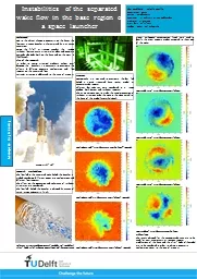
/
Project 2: Study of Separated Flow Project 2: Study of Separated Flow

Project 2: Study of Separated Flow - PowerPoint Presentation

natalia-silvester
natalia-silvester . @natalia-silvester
Follow
419 views
Uploaded On 2016-07-30

Project 2: Study of Separated Flow - PPT Presentation

in a Low Pressure Turbine Joshua Combs Aerospace Engineering Junior University of Cincinnati Devon Riddle Aerospace Engineering Senior University of Cincinnati ASSISTED BY Michael Cline Graduate Research Assistant ID: 425545

control flow plasma actuators flow control actuators plasma separation pressure jet synthetic actuator university body fluid cylinder discharge turbine

Share:

Link:

Embed:

Download Presentation from below link

Download Presentation The PPT/PDF document "Project 2: Study of Separated Flow" is the property of its rightful owner. Permission is granted to download and print the materials on this web site for personal, non-commercial use only, and to display it on your personal computer provided you do not modify the materials and that you retain all copyright notices contained in the materials. By downloading content from our website, you accept the terms of this agreement.


Presentation Transcript

Slide1

Project 2: Study of Separated Flow in a Low- Pressure Turbine*

Joshua Combs, Aerospace Engineering, Junior, University of CincinnatiDevon Riddle, Aerospace Engineering, Senior, University of CincinnatiASSISTED BY:Michael Cline, Graduate Research AssistantDr. Kirti Ghia, Faculty Mentor*Sponsored by the National Science FoundationGrant ID No. DUE-0756921

1Slide2

Project GoalsGoal 1: Understand the phenomenon of flow separation on streamlined bodies.

Goal 2: Understand methodologies for analyzing and controlling flow separation.2Slide3

ObjectivesObjective 1: Investigate characteristics of the low-pressure turbine.

Objective 2: Explore methods of flow separation and control. Objective 3: Disseminate findings in a technical report.3Slide4

MotivationReduce engine weight (COST!!) i.e. use fewer bladesIncreases the amount of work done by each bladeAdverse pressure gradient and low Reynolds number induces flow separation thereby decreasing low-pressure turbine (LPT) efficiency

Must CONTROL flow in LPT to reduce flow separation 4Slide5

TerminologyAdverse Pressure Gradient (APG): Pressure increases in the flow direction

Flow Separation: Detachment from body surface Michael Cline, 2012 AY-REU Program

5

John Anderson, Fundamentals of Aerodynamics, 5thSlide6

Terminology continuedReynolds Number (Re): Dimensionless quantity representing the ratio of inertial forces to viscous forcesIndicates whether flow is laminar or turbulent

Re ≈ 10e5Re ≈ 10e6Transition Region: Zone between laminar and turbulent flow

Boundary Layer (BL):

Thin viscous region adjacent to the body

6

John Anderson, Fundamentals of Aerodynamics, 5thSlide7

Flow Control MethodsTwo main categories:PassiveTrip Wire

Vortex GeneratorsRoughness…There are others, these are just to name a fewActiveBL SuctionSynthetic JetPlasma Actuator7Slide8

Passive ControlTripwirePromotes transition from laminar BL to turbulent BL Increases momentum to overcome APG

(Top-Bottom):“Drag Reduction on Aerodynamic Shapes with Ground Effect”, http://www.aerospaceweb.org/question/aerodynamics/q0228.shtml

Vortex Generator

“Re-energizes” BL

Delays flow separation

8Slide9

Active ControlAdds momentum through a body force.Proven to reattach flow effectively; no fluid injection

Plasma Actuators9Professor Wei ShyyUniversity of MichiganSlide10

Types of Plasma ActuatorsSingle Dielectric Barrier Discharge (SDBD) Plasma ActuatorsGlow Discharge ActuatorsPlasma Synthetic Jet Actuators10Slide11

Single Dielectric Barrier Discharge Plasma ActuatorsWidely utilized Desirable features for use in air at atmospheric pressuresActive airfoil leading edge separation controlControl airfoil dynamic stallBluff body flow controlBoundary layer flow controlInternal and external flow applications.

Effective at high subsonic, transonic, and supersonic Mach numbersTwo electrodes separated by dielectric barrier material. One electrode on aerodynamic surface exposed to airCovered electrode encapsulated in dielectric materialVoltage is applied igniting the DBDUnique: sustain large volume discharge at atmospheric pressure without arcing. Self limiting.Flow control created through generated body force vector field mixing with the external flows momentum. 11Slide12

Experiment using SDBD actuatorsCylinder Side image of the smooth flow closely attached to the cylinder.Close up on the flow behind the cylinder. Wake is minimized.12

Professor Wei ShyyUniversity of MichiganSlide13

Experiment using SDBD actuators continuedCylinder Side image of flow without the use of SDBD.Close up on the flow behind the cylinder. Wake is large and out of control.13

Professor Wei ShyyUniversity of MichiganSlide14

Plasma Synthetic Jet ActuatorDesigned for flow control that consists of an annular electrode in quiescent and flat plate boundary layer flows. SJA formed from the working flow of the systemName came from:Circular plasma region produced on the actuation generates vertical zero-net mass flux (synthetic) jet. Actuator pulses forming a starting vortex ring.

Advects ahead of jet and secondary vortex rings near actuator surface. Pulsing frequency is varied, creating multiple vortex ringsVortex ring interactionsIncreases peak velocityIncreases streamwise extent of the jet.14Slide15

Experiment using Synthetic Jet ActuatorsInvestigating plasma actuators and synthetic jets to develop a plasma flow control device that is more effective. Observed varied pulse frequencies and jet characteristicsPeak velocitySteady operation of the actuator without pulse frequenciesConstant velocity

15Slide16

Experiment using Synthetic Jet Actuators continuedBoth graphs show the streamwise distribution of local maximum mean axial velocity Peak velocity pulsing at 10 HzOptimum time of operation is less than 24 msInteresting observation being that it never returns to zero velocitySuggests optimum operational frequency closer to 10 Hz.

16Slide17

Computational Fluid DynamicsMethod of analyzing fluid mechanics with theoretical and experimental techniquesUtilizes algorithms and numerical methods to solve and analyze fluid flow problemsComputer carries out the calculations of time dependent interactions between the body and the fluid

17Slide18

Generate “baseline” results for the LPTLearn how to model flow and implement into ANSYS Fluent (CFD software)Learn to used programming languages required for CFD (i.e. C++)18

…Future WorkSlide19

Timeline

Weeks:12345 6 78910111213Learn characteristics of turbine

Understand

flow separation

Understand transition

of flow

Study flow control strategies

Poster

Final Report

Journal

Paper

Due Final Day

19Slide20

Questions?Slide21

Referenceshttp://projei.tistory.com/47Huan, Junhui, Separation Control Over Low Pressure Turbine Blades Using Plasma Actuators, University of Notre Dame, 2005

Hilbert, Brian F., Drag Reduction on Aerodynamic Shapes with Groudn Effect, Clarkston University, 2011Xiaoping Xu, Zhou Zhou, Ruijun Fan, Junli Wang, Investigation of Active Flow Control on Aerodynamic Performance of HALE UAV Airfoil, Second International Conference on Computer Modeling and Simulation, 2010Shin, J., Narayanaswamy, V., Raja, L.L., Clemens, N.T., "Characterization of a Direct-Current Glow Discharge Plasma Actuator in Low-Pressure Supersonic Flow," AIAA Journal, Vol. 45, No. 7, pp. 1596-1605, 2007.