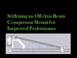
/
Stiffening an Off-Axis Beam Compressor Mount for Improved P Stiffening an Off-Axis Beam Compressor Mount for Improved P

Stiffening an Off-Axis Beam Compressor Mount for Improved P - PowerPoint Presentation

natalia-silvester
natalia-silvester . @natalia-silvester
Follow
392 views
Uploaded On 2016-07-20

Stiffening an Off-Axis Beam Compressor Mount for Improved P - PPT Presentation

DSK Engineering Derek Blash Team Leader Faculty Liason Sarah Hoefker Secretary Kyle Latz Finance Officer Client Liason Client Description Navy Prototype Optical Interferometer NPOI ID: 412013

beam 2011 prototype compressor 2011 beam compressor prototype frequency testing phase client development results research data final 2010 test

Share:

Link:

Embed:

Download Presentation from below link

Download Presentation The PPT/PDF document "Stiffening an Off-Axis Beam Compressor M..." is the property of its rightful owner. Permission is granted to download and print the materials on this web site for personal, non-commercial use only, and to display it on your personal computer provided you do not modify the materials and that you retain all copyright notices contained in the materials. By downloading content from our website, you accept the terms of this agreement.


Presentation Transcript

Slide1

Stiffening an Off-Axis Beam Compressor Mount for Improved PerformanceSlide2

DSK Engineering

Derek

Blash

Team Leader

Faculty

Liason

Sarah

Hoefker

Secretary

Kyle

Latz

Finance Officer

Client

LiasonSlide3

Client Description

Navy Prototype Optical Interferometer (NPOI)

Naval Research Lab

James H. Clark, III

Started in 1990

Optomechanical

Lead Designer

Naval Research Lab/Lowell Observatory

Joel

Dugdale

NPOI Mechanical Engineer

Academic Advisor

Dr. Ernesto

Penado

Chair of Mechanical Engineering Slide4

What is NPOI?Slide5

What is the Big Beam Compressor?

Placed between

siderostat

mirror and vacuum tube

Compresses the

14in

beam to 5in beam

More photons per square inchSlide6

Problem Definition

Beam compressor begins to vibrate at a low frequency which disturbs the beam of starlight

Verify finite element analysis (FEA) presented in client/advisor’s paper

Project Goal

: To design and modify the current beam compressor to increase its fundamental frequency and reduce the amplitude of the vibrations increasing visibility from 7,000 to 70,000 stars.Slide7

Specifications

Weight Limit (Beam Compressor)

Must not exceed

258

pounds (or

10%)

Materials

Aluminum

6061 thin walled tubing

Material dimensions

1 inch diameter with .0625 inch wall thickness

Budget

$300

Mounts

4

Frequency

Within 30% of desired 128 HzSlide8

State of the Art Research

“Stiffening an off-axis beam compressor mount for improved performance” published by Ernesto Penado, James H. Clark, III, and Frank Cornelius

ISOTRON accelerometers

Endevco

website

National Instruments

LabView manual

Mechanical Vibrations

by S.S.

RaoSlide9

Budget

Allocated Budget: $300

Material

Price

Purchased From

Aluminum Tubing

$104

Industrial Metal

Supply

Hardware

$7

Copper State Nut & Bolt

Computer Costs

$75

Data Doctors

Poster Mounting

$60

Michael’s

Total Cost

$246Slide10

Schedule

Phase 1: Research (9/27/2010 - 10/25/2010)

Phase 2: Design and Manufacture Support Modifications (10/11/2010

-

3/1/2010)

Phase

3: Testing for Max Displacements of Beam Compressor (3/1/2011 – 3/19/2011)

Phase 4: Data Reduction (3/19/2011 – 4/1/2011)

Phase 5: Prep for possible Optics Lab testing (4/22/2011-5/8/2011

)

Total Hours

: 240 hours (Jan-April 2011)Slide11

Deliverables

Memo showing final prototype for structural members (2/17/2011)

Memo describing our testing results (4/1/2011)

Reports with Tables and Graphs Comparing Actual Data to Predicted Data (4/17/2011)

Final Presentation/Poster (4/29/2011)

Final Capstone Paper (5/6/2011)Slide12

Concept Development

Prototype 1

: Machined joint/end attachmentSlide13

Concept Development

Prototype 2

: NASA joint Slide14

Concept Development

Prototype 3

: Crimped tubing (Rounded edges)

*Desired by Client*

Cracked: Unable to useSlide15

Actual Development

Prototype 4:

Plugged ends to prevent crushing

Open source loadingSlide16

Testing

Tested max displacement

points

Tested other points

LabVIEW

VI (virtual instrument

)Slide17

Testing Results

Test Cases

Frequency (Hz)

FEA Actual

Difference

% Error

1

17.4

13.3

4.1

23.6

2

33.2

31.0

2.2

6.6

3

36.1

32.0

4.1

11.4

4

66.5

60.0

6.5

9.8

5

113.7

84.4

29.3

25.8

6

127.6

95.9

31.7

24.8

7

>127.6

97.3

30.3

23.7

Frequencies (Hz)

Test Cases

FEA

Actual

Difference

% Error

1

17.4233.2336.1466.55113.76127.6Slide18

Results

Original Frequency: 13.3 Hz

Final

Frequency: 97.3 HzSlide19

Conclusion

Final Weight: 257.4 lbs (<10%)

Test Results within 30%

4 points of contact

RecommendationsSlide20

Questions?